MTRotator Motion Check
Overview
This procedure checks the motion of the MTRotator under nominal movements, issued independently from the LOVE/MTQueue or the MTRotator EUI.
The most common occurrences that will require moving MTRotator directly are:
Resetting the rotator’s position to avoid boundary limits while Simonyi is tracking.
Moving the rotator to 0 deg in preparation for a filter change/swap.
Realigning the rotator to the position of the Camera Cable Wrap (CCW).
Warning
This check cannot be accomplished if MTRotator is in FAULT on the CSC and/or with interlocks
activated on the GIS or the MTRotator EUI. Please refer to MTRotator Recovery
Procedure to clear these warnings before proceeding.
Using MTQueue & SAL Scripts
Run the maintel/mtrotator/move_rotator.py SAL script on LOVE/MTQueue using the following configuration:
maintel/mtrotator/move_rotator.py¶angle: <final_angle_in_degrees>
# Final rotator angle in degrees.
# Allowed range: [-90°, +90°].
Changing Rotator Velocity
Whenever the MTRotator CSC is newly enabled, the rotating velocity resets to its default value (3.5 deg/s).
If you need to move the Rotator with another velocity, issue a run_command.py directly after enable the CSC.
The recommendation is 0.5 deg/s.
maintel/run_command.py¶component: MTRotator
configureVelocity
parameters:
vlimit: 0.5
If this procedure fails, proceed to using the MTRotator EUI.
Using the MTRotator EUI
Enter the virtual machine that controls the rotator (hexrot-vm01.cp.lsst.org) with your IPA account credentials, and access the MTRotator GUI.
Note
Remote Access: The How to Access MT M2/Rotator/Hexapods/Dome EUI has a detailed procedure for accessing all the GUIs in the virtual machine.
Summit Access: If you are logged into a linux machine at the summit, you can enter the virtual machine using an SSH command.
Open a terminal from the ‘Activities’ tab on top left, and type the following command:
ssh -Y hexrot-vm01.cp.lsst.org
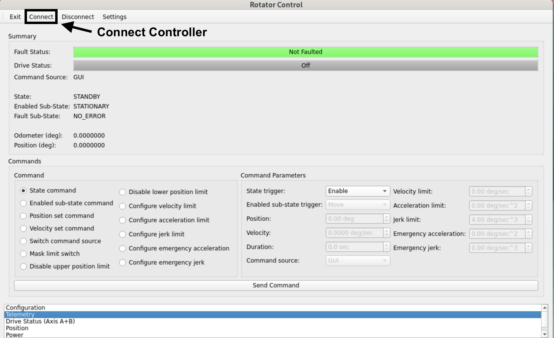
MTRotator Python GUI (Controller Connected)
Once in the Rotator Control GUI, Connect to the low-level controller (top-left), and change the
Command SourcetoGUI.In the
Commandsection of the GUI, select Switch command source.Under the
Command Parametersgo toCommand Sourceand select GUI.Execute the command by clicking Send Command at the bottom of the GUI.
Check the rotator has to following configuration in the
Summarysection of the GUI:State: ENABLED Enabled Sub-State: STATIONARY Fault Sub-State: NO_ERROR
If the
Stateis inStandby, you can enable the rotator as follows:Select State command under the
Commandsection.Go to
Command Parameters, and underState triggerselect Enable.Execute the command by clicking Send Command.
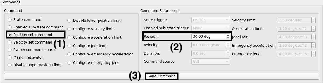
To move the MTRotator using the GUI:
Choose a final position for the rotator:
Select Position set command in the
Commandsection.Under
Command Parameters, navigate toPositionand input a value between +/- 90 degrees.Execute the command by clicking the Send Command button.
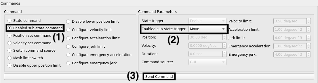
Command the rotator to move to final position:
Select Enabled sub-state command in the
Commandsection.Under
Command Parameters, navigate toEnabled sub-state triggerand select Move.Execute the command by clicking the Send Command button.
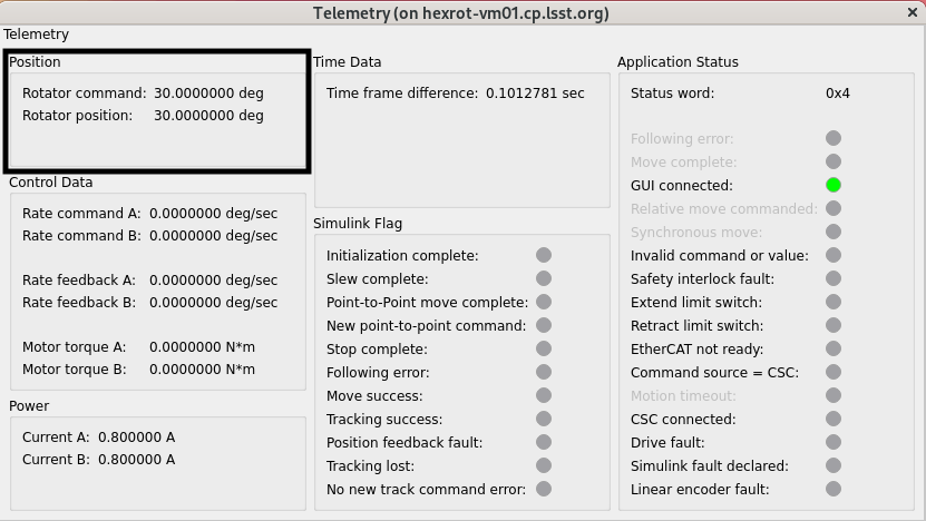
Verify that the rotator is at commanded value by checking the
PositionunderSummary.
If the MTRotator does not follow:
Transition to
Standbystate (step 3) followed by theEnabledstate again to reset the internal calculation of Simulink model. Then, move the rotator (step 4) to the specified position again.It might also be possible that some internal signals are not triggered in Simulink module. You can try moving the rotator a smaller distance, first (1 or 2 degrees away from its current position). If the MTRotator moves then you could move it to the specified position.
Warning
MTRotator position should always be at 0 degrees in the Standby state.
Once you are done moving the rotator, change the
Command Sourceback toCSC(step 2); then Disconnect from the controller and Exit the GUI.
This procedure was last modified on Sep 04, 2025.