MTRotator CCW Limit Switches and Pull Cord Alarms
Overview
MTRotator cannot be moved because the camera cable wrap (CCW) is under a limit switch error. This typically occurs in situations where:
The angle of the CCW and the MTRotator is different (TMA Fault code 1012).
The CCW or MTRotator has hit the engineering limit or software limit (TMA Fault codes 1002, 1003, 1010, 1011).
Software Limits
Software limits on the CCW are conservatively set to ensure the CCW continues following the MTRotator within a certain range of angle. The software limit switches (either + or −) are triggered when: \(\boxed{\left|\theta_{CCW} - \theta_{Rot}\right| \geq 2.5\, \text{deg}}\)
Positive/Negative Limit Switches
The positive or negative limit switches (engineering limits) physically safeguard the CCW by preventing it from crossing the maximum positional offset from the MTRotator position. These switches are triggered when: \(\boxed{\left|\theta_{CCW} - \theta_{Rot}\right| \geq 5\, \text{deg}}\)
Error Diagnosis
When this issue happens during operations, MTRotator is usually available and MTMount can still be enabled. However, the an error occurs directly with the CCW, reporting itself in fault due to the MTRotator and CCW positions not coinciding. Common alarms for when the MTRotator and CCW are misaligned are:
The D-8 CCW Interlock is triggered on the Global Interlock System (GIS) display, located on level 2.
The TMA IS is triggered on the GIS, and the Watchdog (WD) box in the Safety System of TMA EUI is red,
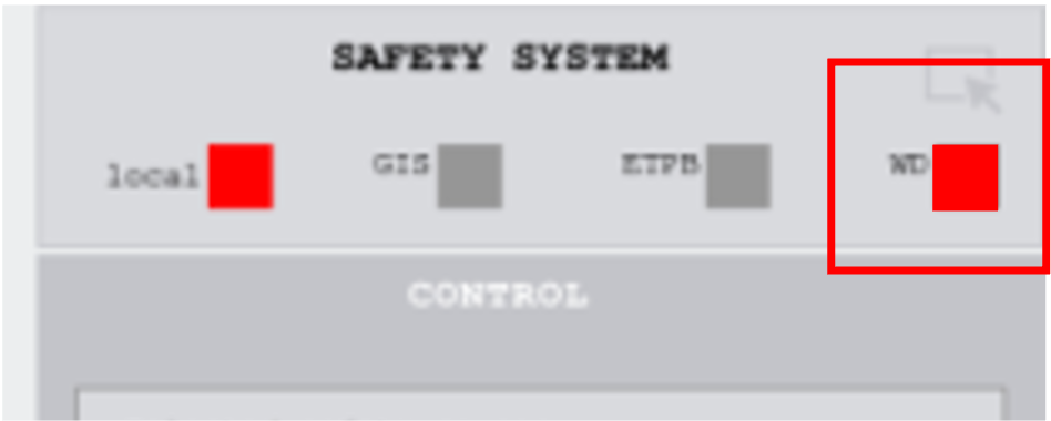
Active Watchdog (WD) alarm in the Safety System.¶ |
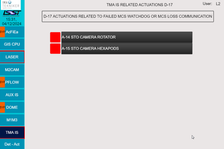
Active TMA IS alarm in the GIS.¶ |
There are five possible cases in which the CCW faults:
Case I: The pull cord alarms (+ and/or −) are active in the SAFETY SYSTEM of the TMA EUI.
Case II: The limit switches (+ and/or −) are activein the CCW INTERLOCKS of the TMA EUI.
Case III: The software limit switches (+ and/or −) are active in the CCW INTERLOCKS of the TMA EUI.
Case IV: At least one limit switch and one pull cord alarm is active.
Case V: All limit switches (Cases II and III) and pull cord alarms (Case I) are active (rare under normal circumstances).

Pull cord +/- alert highlighted by the red box in the SAFETY SYSTEM.¶ |
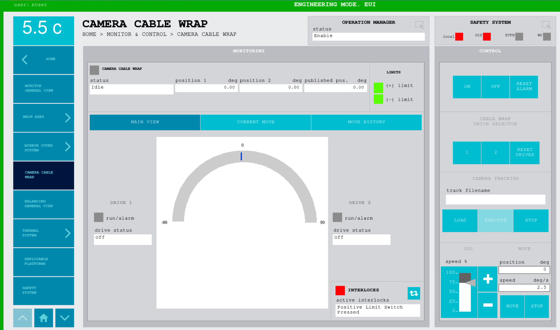
Positive limit switch alert highlighted by the red box in the CCW INTERLOCKS.¶ |
Preconditions
MTMount is in
DISABLEDand the TMA EUI is inEngineering mode.MTRotator is in
DISABLED.
Note
There are two ways to recover this fault:
Moving the CCW to the Camera Rotator (see the Procedure Steps below).
Moving the Camera Rotator to the CCW (see the MTRotator Manual Rotation Procedure for instructions).
Procedure Steps
Warning
A safe speed to move the CCW through the EUI should be \(\, \boxed{\ll \, 5 \, \text{deg/s}}\).
ALWAYS move the CCW as close as possible to the MTRotator.
It is always recommended to DISABLE both software and engineering limit switches.
Case I: Pull Cord (+ / −) Alarms Are Active
These switches are related to the TMA Safety System, and they check that the difference between the CCW and the rotator is not too high. Although it is an independent safety system designed for the safety of the TMA operating personnel, it is sometimes used to safeguard valuable TMA hardware components — like in this case.
Even though this procedure is done entirely in the EUI, the command actually goes to the PILZ safety system and NOT to PXIs.
Fault Check
The safety matrix in HOME → MONITOR & CONTROL → SAFETY SYSTEM shows
an active Pull Cord + or Pull Cord − alarm.
If the D-8 CCW interlock is triggered, bypass the detection through the GIS panel.
In the TMA EUI, select HOME → MONITOR & CONTROL → SAFETY SYSTEM.
Select the row
Pull Cord +orPull Cord −(whichever is shown to be active), and click the softkey SET OVERRIDE.This should change the color of the pull cord alarm from red to purple.
You will have exactly 3 minutes to override the alarm before it activates again.
Move the CCW to the MTRotator position:
Go to HOME → MONITOR & CONTROL → CAMERA CABLE WRAP and select the RESET ALARM blue softkey.
Turn ON the CCW drives; the
statusshould showEnabledin green.Jog the CCW to the current MTRotator angle using the + / - blue softkeys.
Note
You can ONLY JOG the CCW under an alarm-override state.
Turn OFF the drives; the
statusshould showIdle.
Go back to HOME → MONITOR & CONTROL → SAFETY SYSTEM.
- Select the row
Pull Cord +orPull Cord −and click the softkeyRELEASE OVERRIDE. This should turn the alarm from purple back to red.
Click the softkey RESET SELECTED. This should clear the pull cord alarm completely.
Make sure to clear the camera rotator interlocks, and remember to remove the bypass on the D-8 CCW detection (if bypassed).
ENABLEMTRotator from the CSC, followed by MTMount.
Case II: Limit Switches (+ / −) Are Active
The maximum range of movement for the CCW is decided by the range of motion of the MTRotator.
Sometimes a difference between these two (e.g., unresponsive CCW) can cause this limit to be triggered either in the
+ve or -ve direction.
Fault Check
The INTERLOCKS block in HOME → MONITOR & CONTROL → CAMERA CABLE WRAP
should show an active interlock of either Positive Limit Switch Pressed or Negative Limit Switch Pressed.
This fault will indicate where you need to edit the Positive or Negative settings in the procedure steps.
If the D-8 CCW interlock is triggered, bypass the detection through the GIS panel.
Go to HOME → SETTINGS → CAMERA CABLE WRAP SETTINGS.
Depending on which limit switch interlock is activated, select the row that says
Positive Limit Switch Enable/Negative Limit Switch Enablein the first column.Change the
Value(third column) toFALSEand click the blue softkey WRITE. This should show a change in yellow.Select the row that says
Positive Software Limit Enable/Negative Software Limit Enablein the first column.Change the
Value(third column) toFALSEand click the blue softkey WRITE. This should show the change in yellow.
Move the CCW to the MTRotator position:
Go to HOME → MONITOR & CONTROL → CAMERA CABLE WRAP and select the RESET ALARM blue softkey.
Turn ON the CCW drives; the
statusshould showEnabledin green.Jog the CCW to the current MTRotator angle using the + / - blue softkeys.
OR enter the angle in the
position degfield with an angular speed \(\, \left(\ll \, 5 \, \text{deg/s}\right)\) in thespeed deg/sfield and select MOVE.
Turn OFF the drives; the
statusshould showIdle.
Make sure to clear the camera rotator interlocks, and remember to remove the bypass on the D-8 CCW detection (if bypassed).
ENABLEMTRotator from the CSC, followed by MTMount.
Case III: Software Limit Switches (+ / −) Are Active
The maximum range of movement for the CCW is decided by the range of motion of the MTRotator.
Sometimes a difference between these two (e.g., unresponsive CCW) can cause this limit to be triggered either in the
+ve or -ve direction.
Fault Check
The INTERLOCKS block in HOME → MONITOR & CONTROL → CAMERA CABLE WRAP
should show an active interlock of either Positive Software Limit Switch Pressed or Negative Software Limit Switch Pressed.
This fault will indicate where you need to edit the Positive or Negative settings in the procedure steps.
If the D-8 CCW interlock is triggered, bypass the detection through the GIS panel.
Go to HOME → SETTINGS → CAMERA CABLE WRAP SETTINGS.
Depending on which limit switch interlock is activated, select the row that says
Positive Limit Switch Enable/Negative Limit Switch Enablein the first column.Change the
Value(third column) toFALSEand click the blue softkey WRITE. This should show a change in yellow.Select the row that says
Positive Software Limit Enable/Negative Software Limit Enablein the first column.Change the
Value(third column) toFALSEand click the blue softkey WRITE. This should show the change in yellow.
Move the CCW to the MTRotator position:
Go to HOME → MONITOR & CONTROL → CAMERA CABLE WRAP and select the RESET ALARM blue softkey.
Turn ON the CCW drives; the
statusshould showEnabledin green.Jog the CCW to the current MTRotator angle using the + / - blue softkeys.
OR enter the angle in the
position degfield with an angular speed \(\, \left(\ll \, 5 \, \text{deg/s}\right)\) in thespeed deg/sfield and select MOVE.
Turn OFF the drives; the
statusshould showIdle.
Make sure to clear the camera rotator interlocks, and remember to remove the bypass on the D-8 CCW detection (if bypassed).
ENABLEMTRotator from the CSC, followed by MTMount.
Case IV: (Software) Limit Switch and Pull Cord Alarm is Active
Fault Check
This type of fault requires two conditions:
The
INTERLOCKSblock in HOME → MONITOR & CONTROL → CAMERA CABLE WRAP should show an active interlock of at least one of the following:A
Positive Limit Switch PressedorNegative Limit Switch Pressedinterlock.A
Positive Software Limit Switch PressedorNegative Software Limit Switch Pressedinterlock.
The safety matrix in HOME → MONITOR & CONTROL → SAFETY SYSTEM shows an active
Pull Cord +orPull Cord −alarm.
ALWAYS resolve the pull cord alarms first and then proceed to clear the limit switch interlocks, if still active.
If the D-8 CCW interlock is triggered, bypass the detection through the GIS panel.
Follow steps 1-4 of the Case I procedure to resolve the pull cord alarms.
If the limit switch interlocks are still active, follow steps 1-2 in the Case II or Case III procedure, as appropriate.
Make sure to clear the camera rotator interlocks, and remember to remove the bypass on the D-8 CCW detection (if bypassed).
ENABLEMTRotator from the CSC, followed by MTMount.
Case V: ALL Limit Switches AND Pull Cord Alarms Are Active
If all pull alarms and limit switches are active, this is an indication that there is an EtherCAT line issue. Recover the EtherCAT line will require:
Physically connecting the Beckhoff master to the EtherCAT line to recover it (explained in Reset EtherCAT in TMA Cabinets).
Resetting the TMA PXI.
However, this will often be accompanied by failures/faults in other TMA components controlled by that PXI.
Note
Connecting the Beckhoff master is the most reliable EtherCAT recovery method, but it is not always required. For alternative recovery methods, refer to the EtherCAT line management documentation and the EtherCAT line diagnostic documentation.
Post-Condition
On the TMA EUI: CCW drives show STATUS either
IdleorEnabledif the MTMount is enabled.
Contingency
If the procedure was not successful, report the issue in #summit_simonyi and tag Julen Garcia / Alberto Izpizua / Tekniker remote support available at the time.
CCW/Rotator Global Interlock System (GIS) Operations
Engage/Remove Bypass of the D-8 CCW GIS Interlock
Select the Det-Act tab (bottom left of the screen), and press Bypass by the
D-8 Camera Cable Wrap Safety Device Actuateddetection.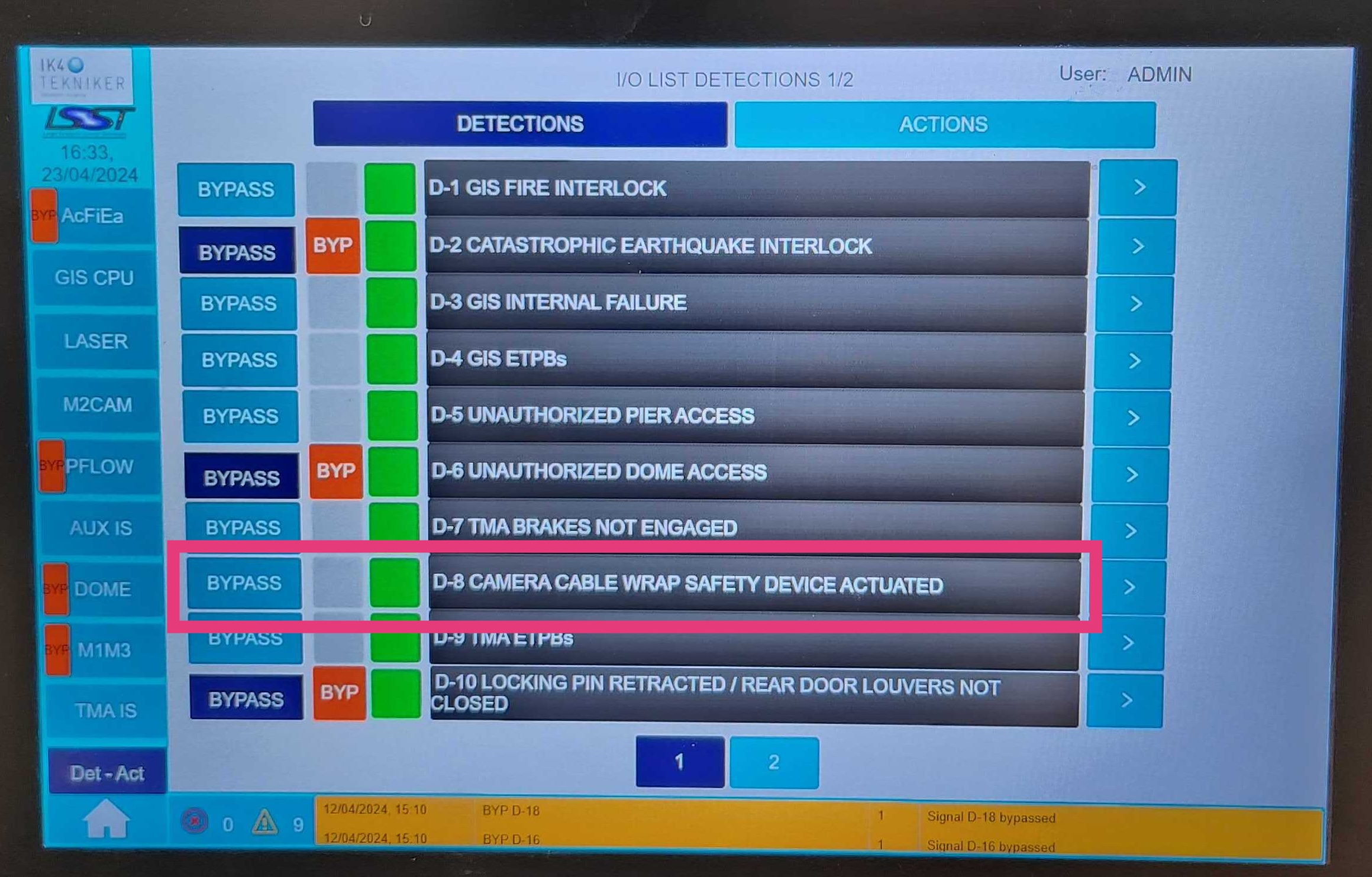
Detection D-8: Camera Cable Wrap Safety Device Actuated
Once all other systems have recovered, select Bypass again to remove the D-8 bypass before normal operations.
Reset Camera Rotator GIS Interlocks
Select the M2Cam tab and then click Overview (default).
Below the
CAM. ROTATORsection, press and hold the Reset button.A green “X” mark should appear next the the
Resetlabel.If it does not show, press and hold the Reset button, again.
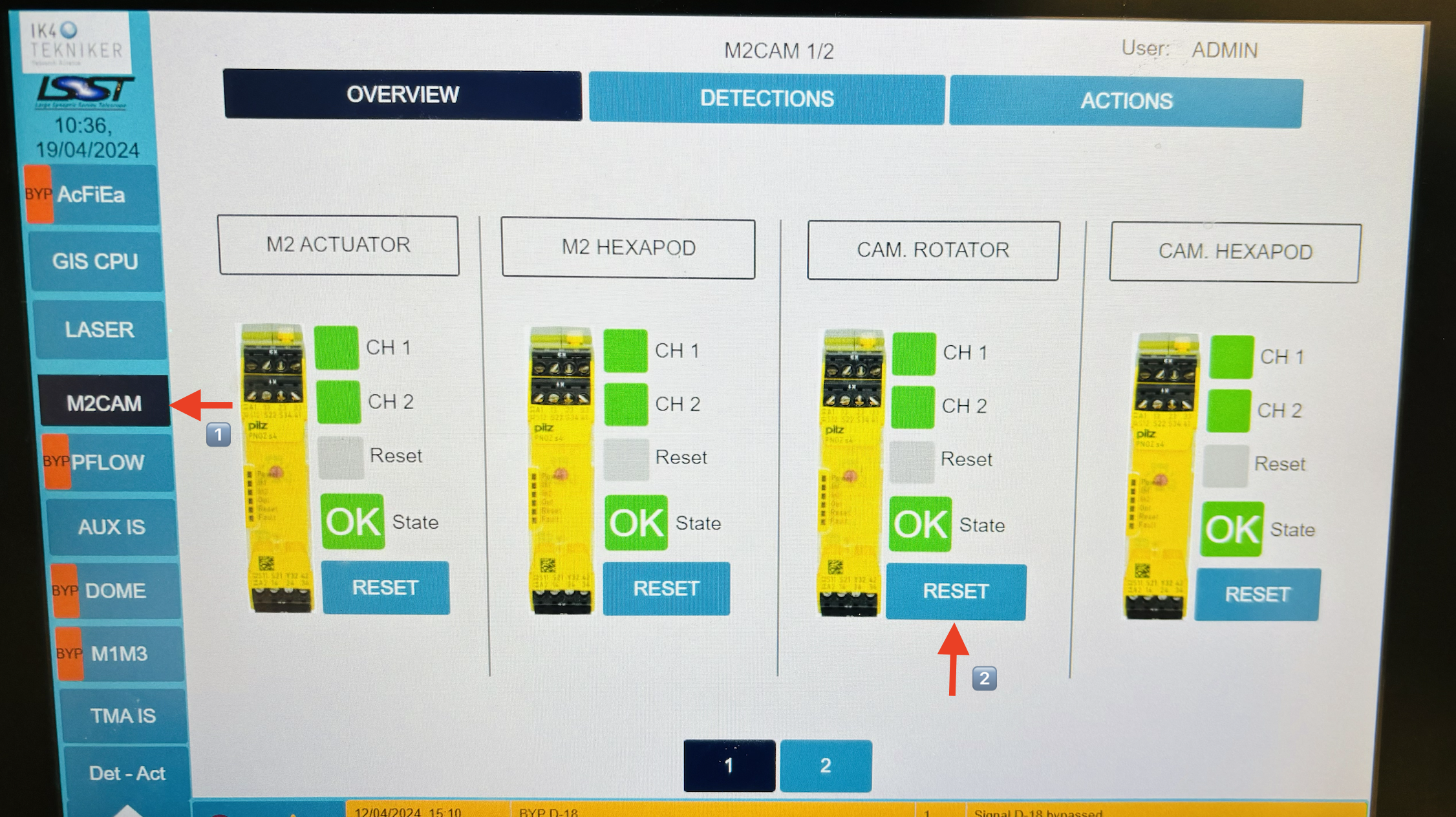
M2Cam GIS Display