GIS
Overview
This document presents an introduction to the General Interlock System (GIS), which plays a crucial role in ensuring safety and efficiency across various subsystems at Vera Rubin Observatory.
First, we provide an overview of the structure of the GIS, outlining its key components and how they interact to maintain operational integrity. Next, we explore the safety matrix of the GIS, detailing the various detections and corresponding actions taken to prevent hazardous scenarios. We describe how users interact with the GIS, including navigating the main controller interface and executing bypass and reset actions when necessary. Finally, we cover troubleshooting procedures to address any issues that may arise, ensuring smooth and uninterrupted operations.
General Interlock system
The GIS is a critical system that communicates with various subsystems to prevent dangerous situations by managing interlocks amongst them.
An interlock serves as a mechanism that prevents a system from proceeding unless specific conditions are met.
Additionally, the implementation of STO (Safe Torque Off) further enhances safety by halting the power supply to the motor when required.
Structure
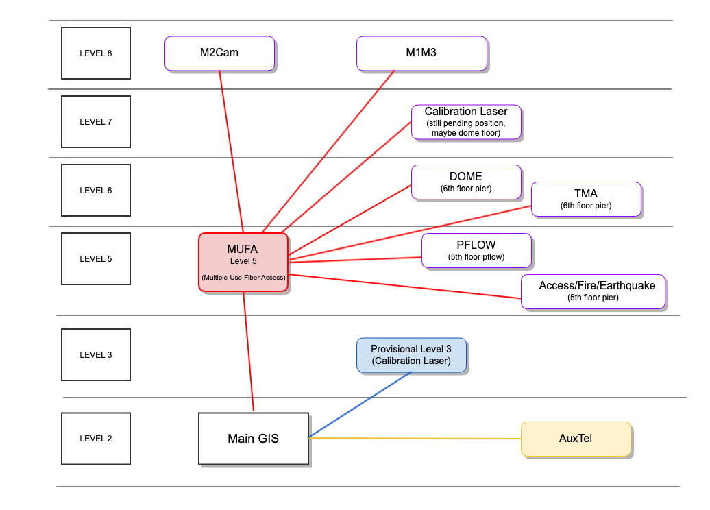
The GIS is composed of a Main Controller (cabinet on level 2) and several cabinets. The Main Controller manages all other cabinets, and user interaction is primarily through the Main Controller interface.
The connection to the subsystems is by:
Network: TMA, Dome, M1M3, AuxTel.
Signals wires: Earthquake, Access control, Pflow lift, Calibration Laser, and the top-end subsystems: M2Cam (that includes M2, M2 Hexapod, Camera Rotator, Camera Hexapod).
TMA, M1M3 and Dome have their own interlock system (IS) but they communicate to the GIS. For instance, if a TMA interlock is triggered, you will see it in the GIS Main controller.
Note
Currently as of June 6 2024, Dome IS is connected to GIS, but the signals between both are bypassed, as integration tests between both systems are still pending.
GIS Design updated on June, 2024
Safety Matrix. Detections and Actions
The GIS uses a safety matrix to manage the interlocks, consisting of detections signals and their corresponding actions for the subsystems.
Detection:
Specific condition or event within a subsystem that is reported to the GIS.
Action:
Response to the corresponding detection, done by the GIS.
Certain detections that could compromise the system trigger an interlock mechanism, which is an action taken to ensure the system’s safety.
Some detections have actions that only indicate their status, e.g. A fire interlock.
Detection |
Action |
|---|---|
|
TMA drives will be STO (Safety Torque Off) and engage the brakes. |
|
|
Interacting with GIS
Main Controller Interface
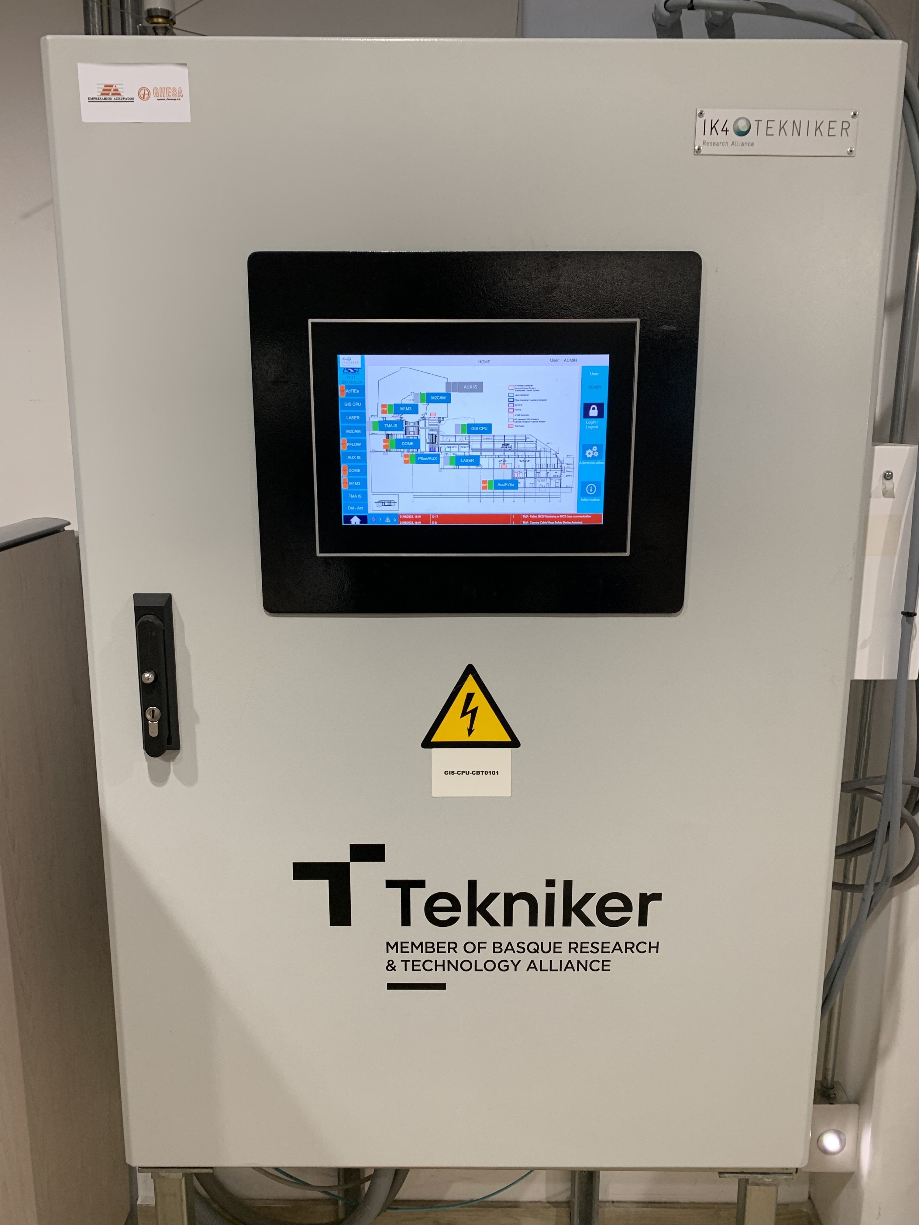
GIS Main Panel Cabinet at level 2
The Observing Specialists will interact with the Main Controller cabinet, located on Level 2.
Occasionally, in the event of system errors, it may be necessary to interact with other cabinets for reboots or power cycling. However, these activities are typically beyond the OS team’s responsibilities.
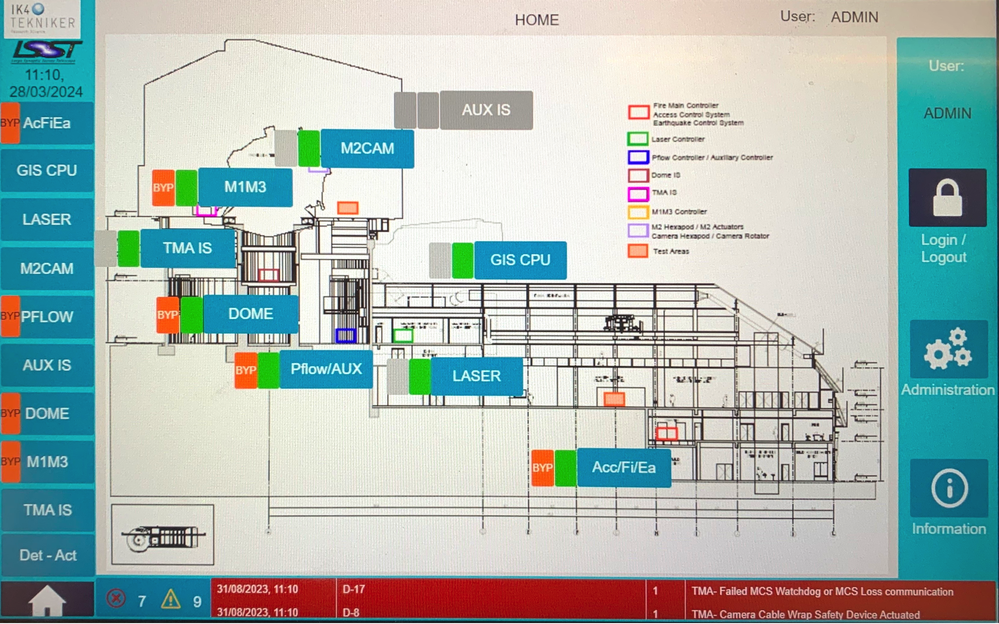
GIS General Overview
The GIS General Overview (home), allows you to see the general status of the safety areas. The navigation bar (left) allows you to navigate between the subsystems.
Some area names are straightforward, while others are:
AcFiEa: Access Control System / Fire Main Controller / Earthquake Control System. The safety gates to the pier intermediate level and to level 8 are referred as access control system.
M2CAM: M2 area, includes the M2 actuator, the M2 Hexapod, the Camera Hexapod and the Camera Rotator.
PFLOW/AUX: Pflow Controller & Auxiliary Elements.
AUX IS: Auxiliary Telescope Controller IS. It only has the action ‘A-22 STO Earthquake Alarm’.
The GIS Detections and Actions window, accessed via the Det-Act button, displays all detections and actions across all systems, making it the most useful for monitoring.
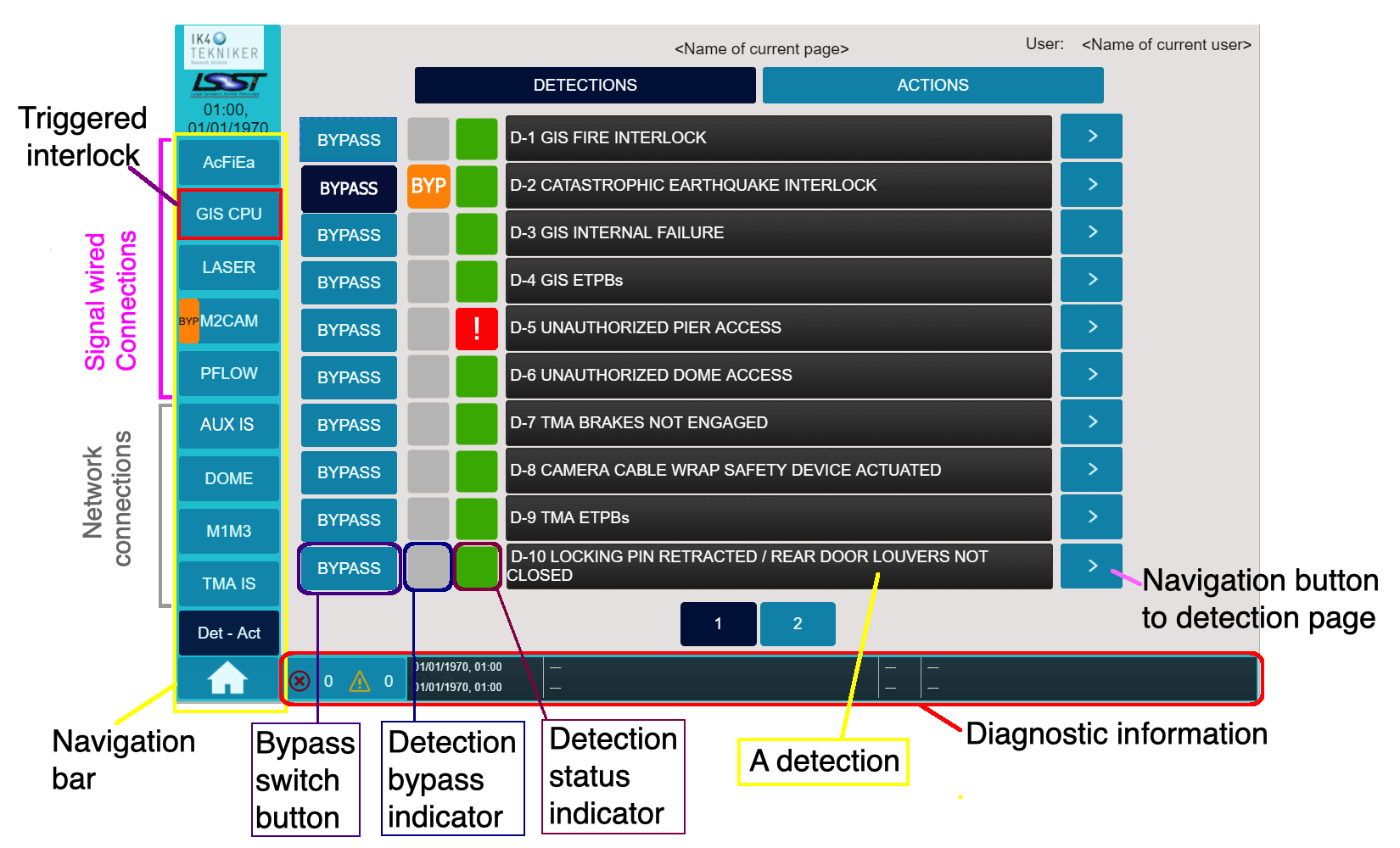
GIS Detections and Actions window
The symbols and their representation are:
 : Indicates the detection is bypassed. It logs alarms but it doesn’t trigger any action.
 : Indicates a triggered interlock.
 : Indicates no interlock is triggered for that detection.
M2 changes in 2024
Addition: Signal D-20 “M2 mirror in closed-loop” as a cause for the action A-5 “Block TMA motion”.
Removal: Signal D-2 “Earthquake Alarm” from A-13 “M2 STO” action signal.
Bypass and reset actions
Any user can reset a subsystem.
Wired subsystems are reset in GIS Main Panel.
E.g Earthquake interlock is reset in the GIS (automatically when the detection dissapears).
Network based subsystems reset on their own in GIS main panel, once the reset is done in the specific subsystem.
E.g. A M1M3 interlock should be reset in M1M3 IS and then it will be clear in GIS main panel.
Only admin user can bypass a subsystem.
Detections can be bypassed but actions cannot.
The ‘D2 earthquake alarm’ may occasionally be bypassed to prevent the TMA from losing power during power or capacitor bank issues. The acceleration threshold for the alarm is approximately 0.3g, which corresponds to a magnitude 5-6 earthquake.
Note
D4 GIS E-stop: Safety gate E-stops are frequently triggered, so they are currently physically bypassed. This bypass will be removed when operations begin.
For more information about safety gates refer to the Safety Gates operation page.
Troubleshooting
To troubleshoot, in addition to understand the system’s structure, you may need to check the alarm logs. Click at the bottom of the Main panel interface to access the Diagnostic Information section. From here you can access the Actual Alarm and the Alarm Log tabs.
Important
Be aware that sometimes the detection disappears, indicating that the interlock is no longer triggered (possibly because someone has reset it), but the action may still be active.
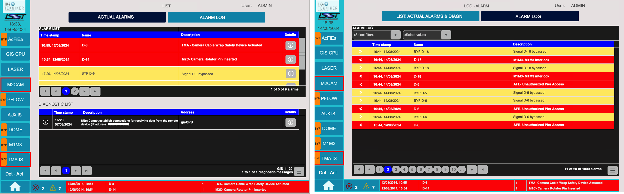
GIS Actual Alarms and Alarm Log tabs.
Note that the time reported for the alarms is still inaccurate and remains a pending issue to be resolved.
Interlocks in GIS Main Control Panel
Remember, depending on the connection type
Wired subsystems are RESET at the GIS Main Control Panel.
Network-based systems require resetting within their corresponding subsystem to clear the interlock in the Main Control panel.
Top End systems
Top End systems (M2CAM), are a special case. The M2CAM - Overview does NOT indicate the status of each individual element, but rather the status of the CIRCUIT that manages the E-stop/STO for each component.
Important
If one of the Top End systems goes to FAULT due to an interlock or after a STO or power cycle, to enable it you must RESET the GIS E-stop status buttons in M2CAM - Overview.
In this case, even if the lights are green (indicating the E-stop circuit is okay), the RESET is still required.
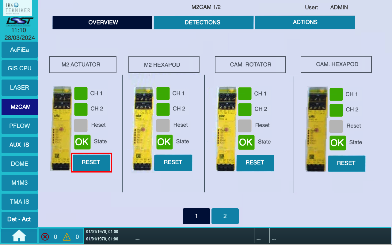
GIS M2CAM - Overview.
The status of CH1 and CH2 in all sytems only have a triggered interlock (indicated by ),
if the E-stop at their cabinet is activated. For M2CAM this cannot happen because it’s disabled.
The M2CAM - Actions tab show the STO Action activation status.
: STO is active, while STO in NOT active.
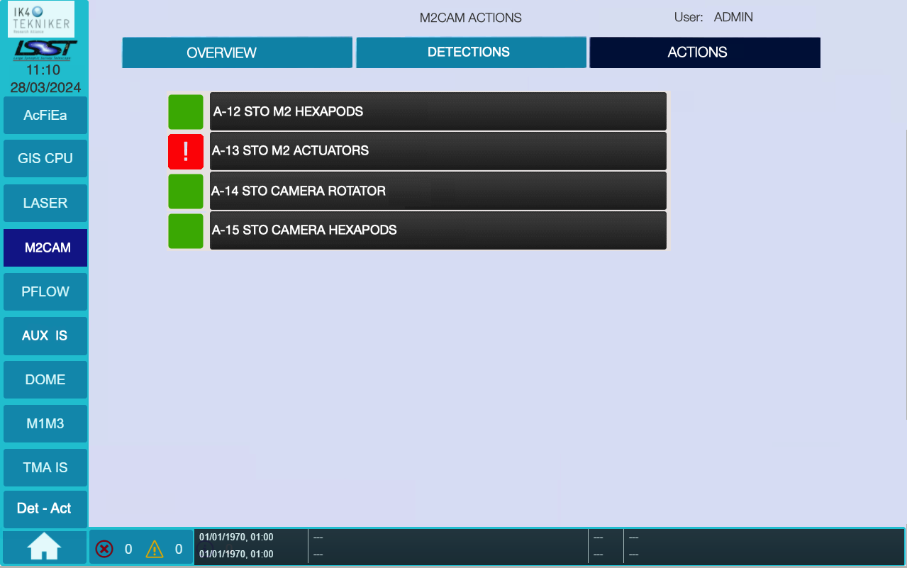
GIS M2CAM - Actions tab shows M2 Actuators STO active.
As an example, to clear ‘A-13 STO M2 Actuators’ action in place (indicated by ), go to M2CAM - Overview and press RESET under ‘M2 Actuator’ (refer to the 2 previous images). After this, the A-13 action status should turn inactive ().
Note that when you press the RESET button in M2CAM - Overview, the Reset status indicator will briefly change from gray to green with a cross. If you don’t see this change, press the button again.
The M2CAM - Detections tab shows the signals: ‘D-14 Camera rotator pin inserted’ and ‘D-20 M2 mirror in closed-loop’.
Triggered interlocks
Some triggered interlocks have an automatic reset, while others may require your input. This is shown in the table below.
GIS signal |
You should: |
|---|---|
D2 Earthquake alarm |
Auto reset (when earthquake stop) |
D3 GIS Internal failure |
Power cycle GIS cabinet |
D4 GIS Estops |
Reset triggered Estop at GIS panel |
D5 Unauthorized Pier access |
Close 6th level safety gate |
D5 Unauthorized Dome access |
Close 7th level safety gate (bypassed, July 2024) |
D7, D8, D9, D17 (TMA signals) |
Reset at TMA EUI |
D10 to D13 (Dome signals) |
Reset at Dome EUI |
D14 Camara Rotator Pin inserted |
Reset at Camara Rotator EUI |
D15, D16 (Pflow signals) |
Auto reset (when lift position changes) |
D18 M1M3 Interlock |
Reset at M1M3 IS |
D19 Man-lift parked |
Not currently used (July, 2024) |
D20 M2 mirror in closed-loop |
Auto reset when M2 is in closed-loop again |
A note on M1M3 IS interface
Both detections and actions can be bypassed.
Any event (detection) will trigger the GIS ‘D18 M1M3 interlock’.
When resetting an event, if it doesn’t work press RESET twice.
See more in M1M3 Interlock System page.
For more information visit the GIS Tekniker page.