MTRotator Recovery
Overview
In the event of a fault occurrence within the MTRotator, following the proper recovery procedure is essential to maintaining operational safety. This document will outline the necessary step-by-step actions to return to normal MTRotator functioning.
Error diagnosis
The difference between the MTRotator and the Camera Cable Wrap (CCW) is too large. Bulkhead limit switch activated; this is also called Pull cord + or Pull cord -.
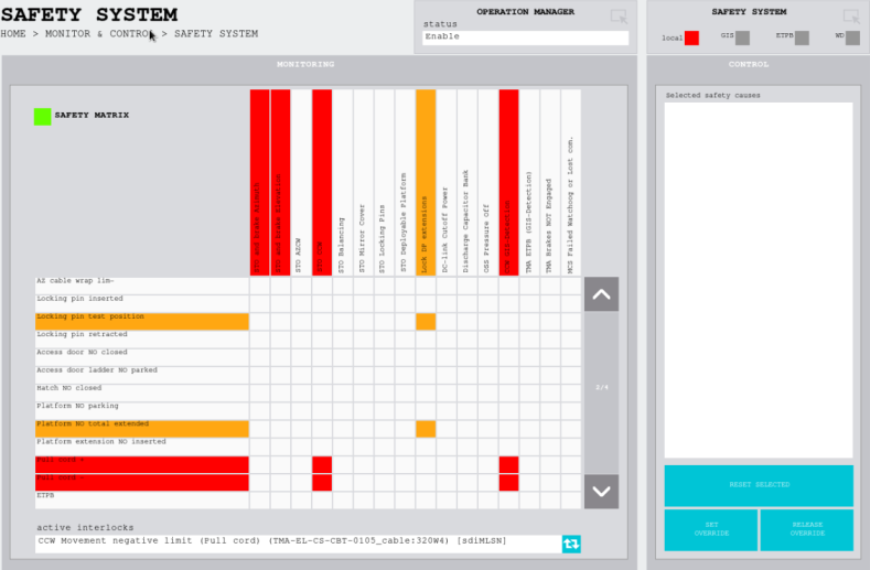
TMA EUI screenshot indicating the pull cord +/- alert highlighted by the red box
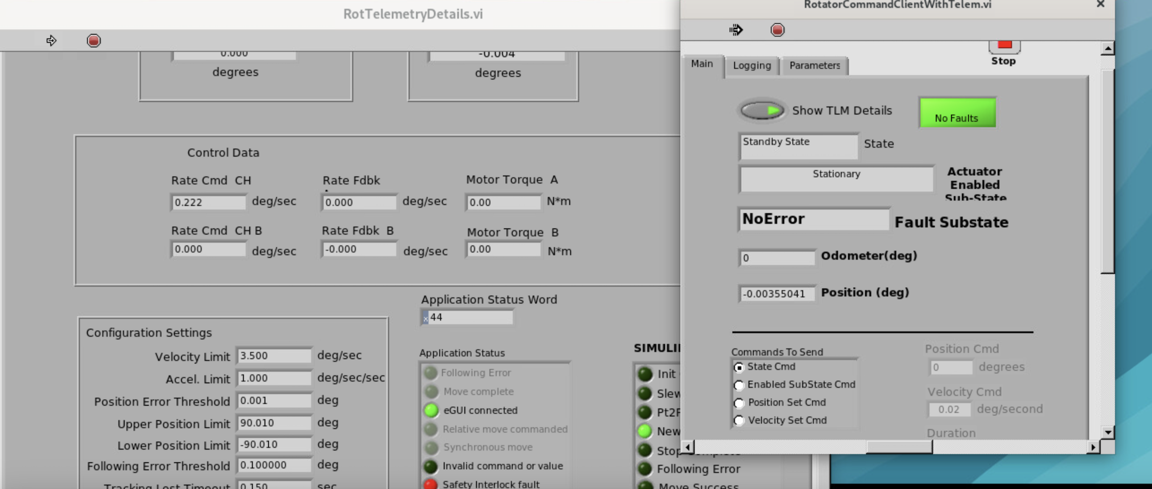
Safety Interlock active in the MTRotator GUI
Simulink fault in the MTRotator GUI
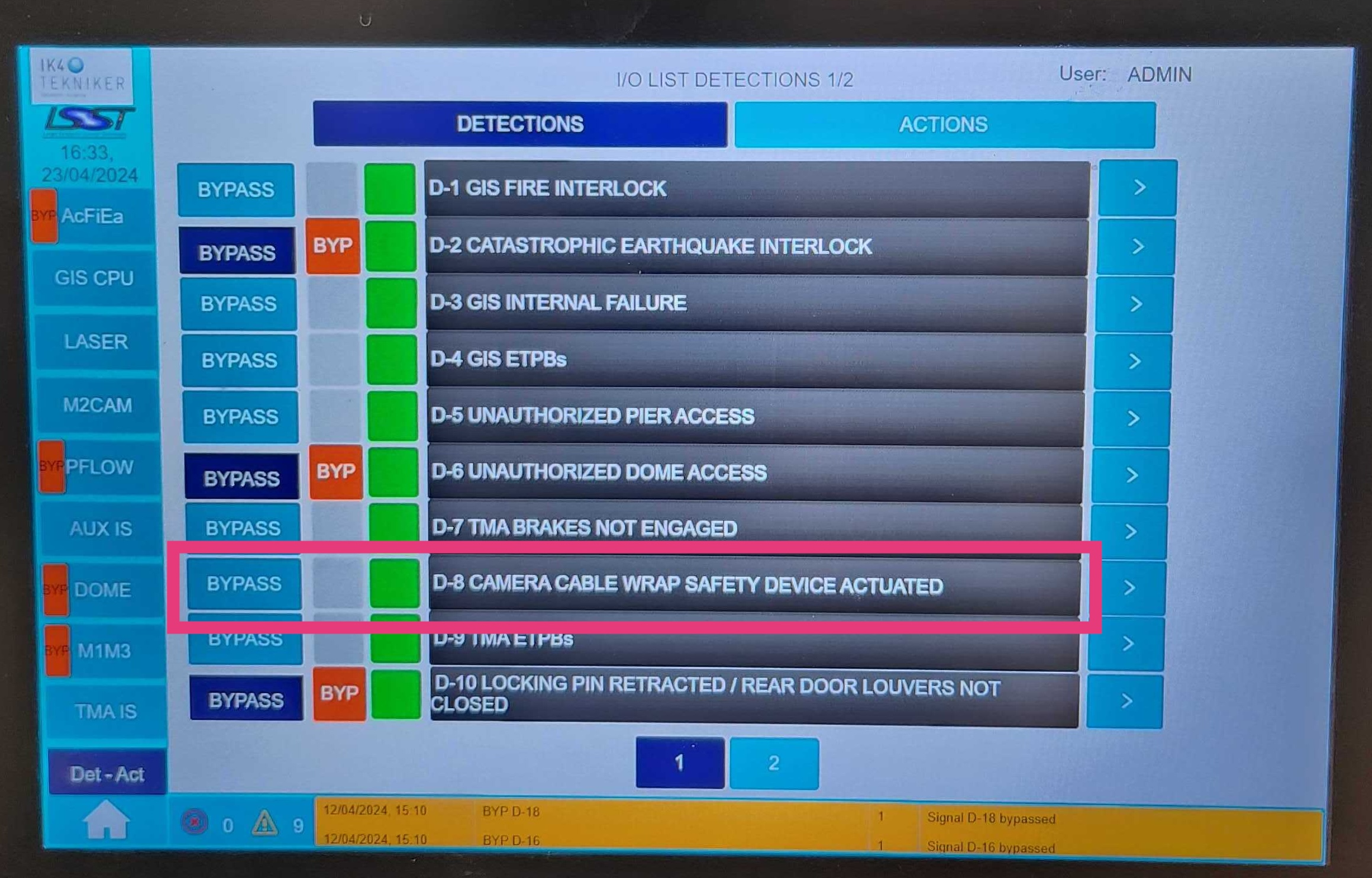
CCW Interlock D-8 activated on the GIS (link here to the GIS interlock screenshot)
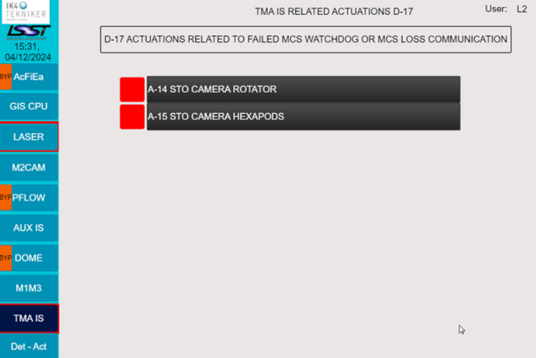
MTRotator CSC goes into
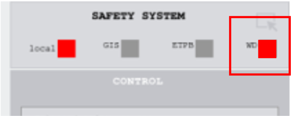
FAULTstate, but it cannot recover or cycle through CSC states from LOVE.Watchdog (WD) box in safety system of TMA EUI is red and GIS TMA IS is triggered.
Note
There are two ways to recover this fault:
Moving the CCW to the Camera Rotator.
Instructions can be found on the CCW Recovery Confluence Page.
Moving the Camera Rotator to the CCW (see the Procedure Steps below).
Procedure Steps
Warning
Only proceed after an accurate assessment of the MTRotator fault is done and details have been documented in a ticket.
Transition MTRotator CSC to
STANDBYstatus.Clear the error from TMA EUI first.
Access the MTRotator EUI/GUI:
Enter the virtual machine that controls the rotator (hexrot-vm01.cp.lsst.org) with your IPA account credentials.
MTRotator Python GUI
Accessing the Rotator GUI
Remote Access: The How to Access MT M2/Rotator/Hexapods/Dome EUI has a detailed procedure for accessing all the GUIs in the virtual machine.
Summit Access: If you are logged into a linux machine at the summit, you can enter the virtual machine using an SSH command.
Open a terminal from the ‘Activities’ tab on top left, and type the following command:
ssh -Y hexrot-vm01.cp.lsst.org
Once in the virtual machine, access the rotator using the run_rotgui command:
[(username)@hexrot-vm01 ~]$ run_rotgui
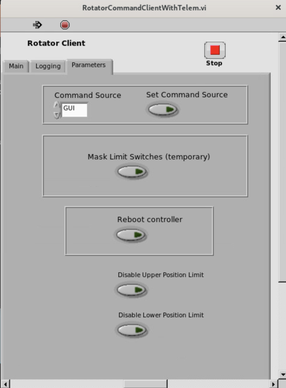
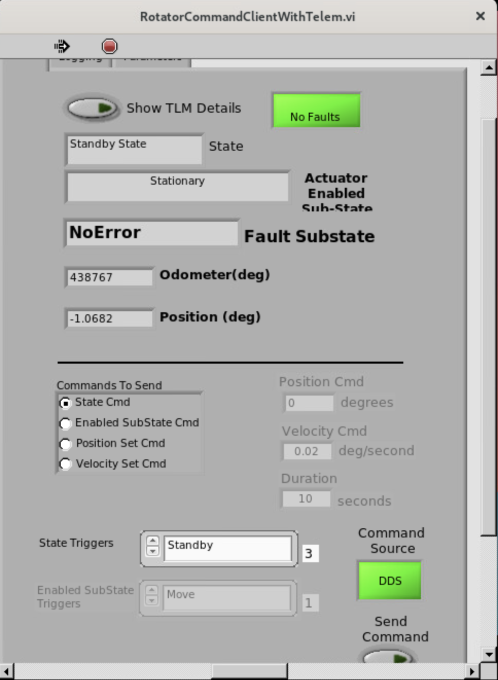
Change the Command Source from CSC to GUI mode:
Once in the Rotator Control GUI, Connect to the low-level controller (top-left).
In the
Commandsection of the GUI, select Switch command source.Under the
Command Parametersgo toCommand Sourceand select GUI.Execute the command by clicking Send Command at the bottom of the GUI.
Clear Simulink error in MTRotator GUI:
In the
Maintab, go to theCommandstab.Under
Command, select State command.Under
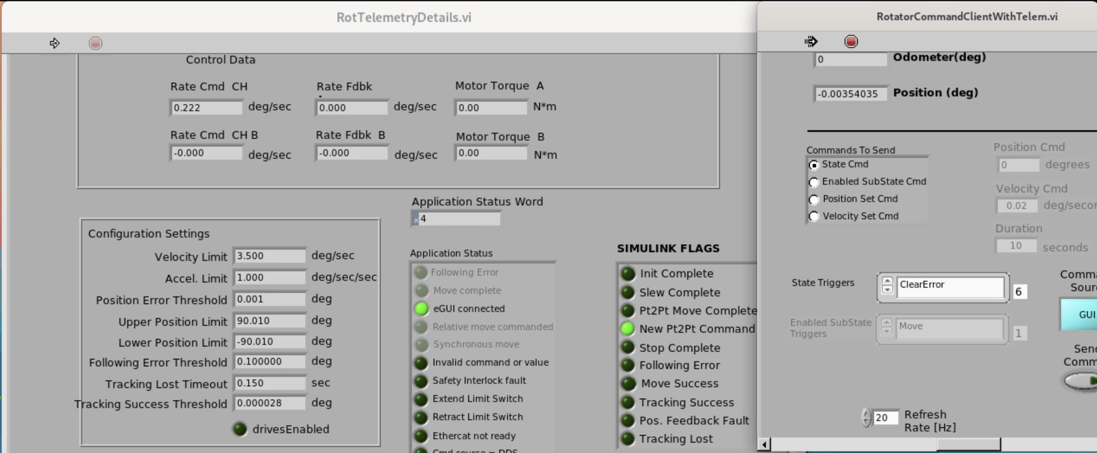
Command Parameters, go toState Triggerand select ClearError.Send the command by clicking on the Send Command button.
Sending ClearError Command
Telemetry Verification
Double-click the Telemetry tab at the bottom of the GUI (see image above).
- If the Safety Interlock is activated, you can find a red light next to theSafety Interlock fault with the
Application Statustab. In case of a Simulink Error, there will be red light next to the Simulink fault on the same page.
Rotator Telemetry with Faults (GUI Command Source)
When both errors are cleared, the telemetry no longer have red fault lights:
Rotator Telemetry without Faults (CSC Command Source)
Reset MTRotator in GIS GUI on Level 2:
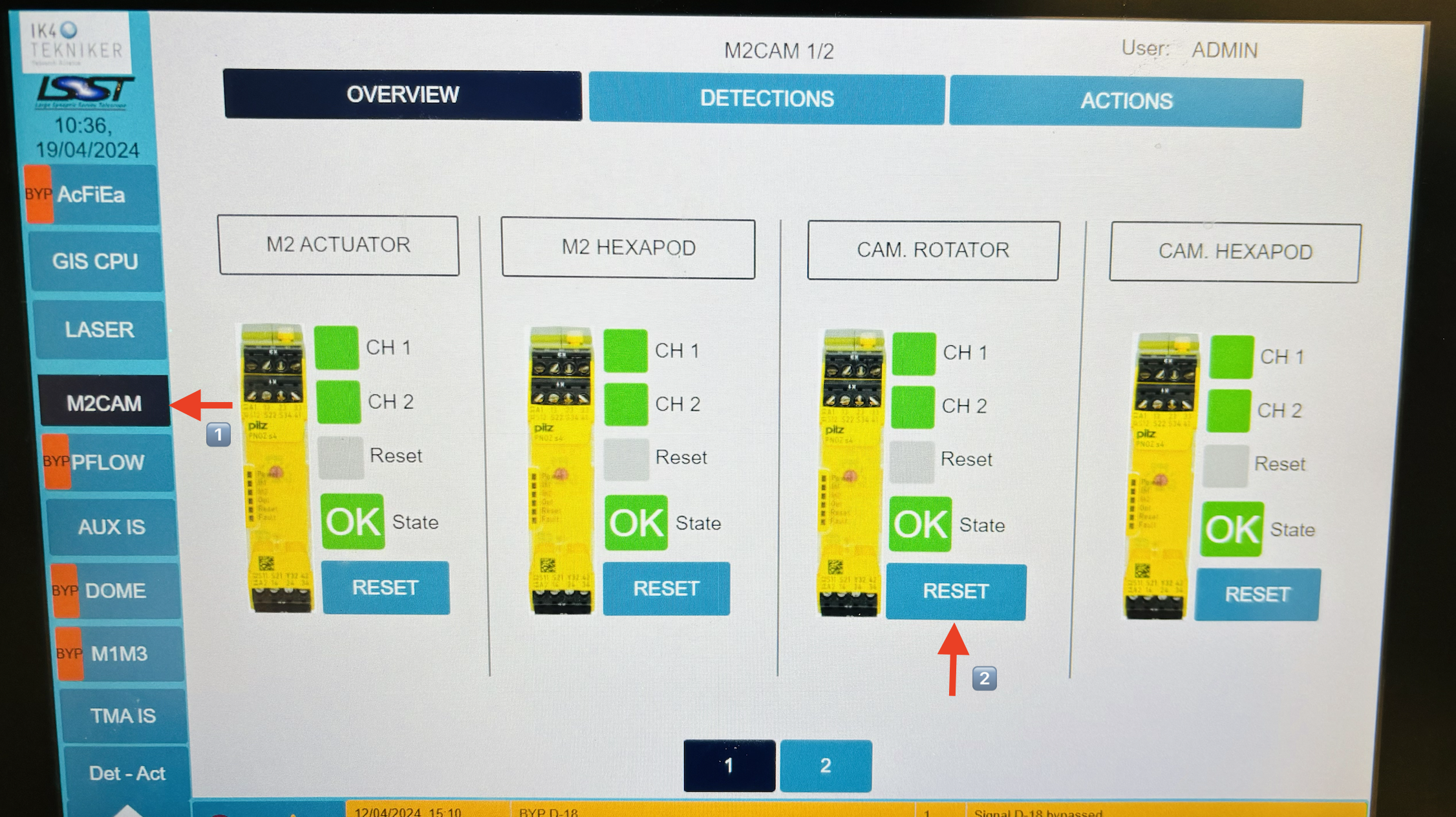
Select the Det-Act tab (bottom left of the screen), and press Bypass by the D-8 (CCW Safety Device Actuated).
- Select the M2Cam tab and then click Overview (default). Below the
CAM. ROTATORsection, press and hold the Reset button. A green “X” markshould appear next the theResetlabel. If it does not show, press and hold theReset button, again.
Enable MTRotator in GUI and Move to CCW:
- Instructions for enabling and moving the rotator are found in steps 3-5of the MTRotator Motion Check procedure.
When selecting an ending position for the rotator, make sure that the rotation distance between the rotator and the CCW are within the software limits:
\[\boxed{\left|\theta_{CCW} - \theta_{Rot}\right| < 2.5^{\circ}}\]Reset Alarms in TMA GUI:
In the Safety System menu, reset the Pull Cord + or Pull Cord - alarm.
Navigate to the Camera Cable Wrap tab, and select Reset alarm.
Release the Bypass to the CCW in GIS GUI on Level 2 (Refer to Step 6a).
Change the Command Source from GUI to CSC mode (reverse procedure of Step 4).
Remember to Disconnect the low-level controller before closing the GUI.
Transition MTMount and MTRotator Back to
ENABLED.
Post-Condition
MTRotator is operational and can be re-enabled from LOVE to safely continue operations.
Contingency
If the above procedure was not successful, inform in the #summit-simonyi channel.
In case EUI/CSC control is not connecting, you could proceed with the control system restart procedure of the MTRotator and MTHexapods PXI controller Reboot (Soft, Hard and Control System Restart).