AuxTel Recovery after Shutdown
Overview
This document describes the procedures necessary to recover the AuxTel systems from a major event. This may include a power shutdown, a major software upgrade, or a loss of network connectivity.
Precondition
These procedures should be applied whenever the AuxTel systems are not operating normally. Not all procedures will need to be followed in every case, and the user should use judgment and only apply the recovery procedures to the systems that are not operating normally.
Note
Ping the machines before trying to recover the system involved. This helps verify their network connectivity and confirms if they are responsive. If the machines respond to the ping, it indicates they are powered on and connected, which can help in diagnosing the issue and determine if a reset or recovery is necessary.
Caution
The preferred method to reset a cRIO is remotely, if not possible, make sure you press the reset button briefly (less than 1 second) to power cycle the cRIO. If you hold it for 5 seconds then it will be factory reset.
Important
Every time you go to AuxTel building do not forget to follow the Safety Entry to AuxTel guidelines.
You need to use a pointed object to press the reset button and reset the cRIOs.
If you need to restart multiple systems that require activating the safety gate bypass, activate it at the beginning and deactivate it once the recovery process for all required systems is complete.
Post-Condition
After completing these procedures, the AuxTel systems should be operating normally.
The safety gate is closed and the bypass is deactivated.
It is recommended to perform a full set of daytime checkouts after completing these procedures to confirm the recovery has been successful.
Procedure Steps
The recovery procedures here are divided into several sections:
Main ATCamera electronics and sensor readout cabinet recovery
The main ATCamera electronics and sensor readout cabinet is on the first floor, next to the chiller, and is shown in Figure 1. Figure 2 shows the inside of this cabinet after opening the door. After a loss of power or other major work, the chiller should start up, but there are typically two things that need to be done, as shown by the yellow arrows in Figure 2:
- The Pfeiffer vacuum gauge will stop reading and stop sending telemetry.
To reset it, press and hold the Up arrow key for 3 seconds. The display should then start reading a vacuum pressure and resume sending telemetry.
- The CryoCon temperature controller will stop controlling.
To resume control, press the Control button on the front panel. The blue light will come on. Typically, when first pressed, there is short Overtemp excursion and the blue light goes off. In this case press it again.
The goal is for the blue light to come on and stay on. It may take 2-3 tries for it to stay on.
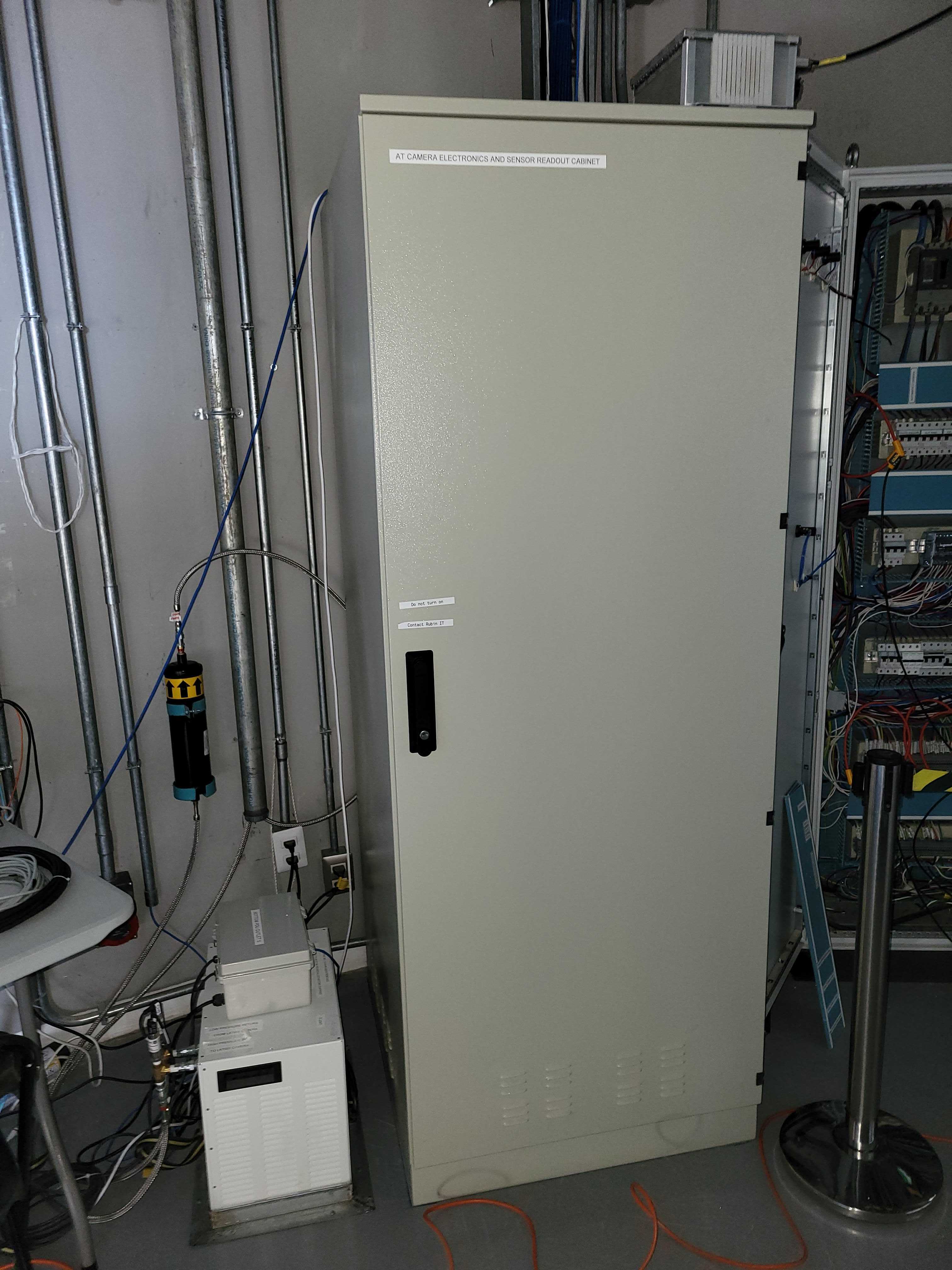
Figure 1: Location of ATCamera main electronics cabinet.
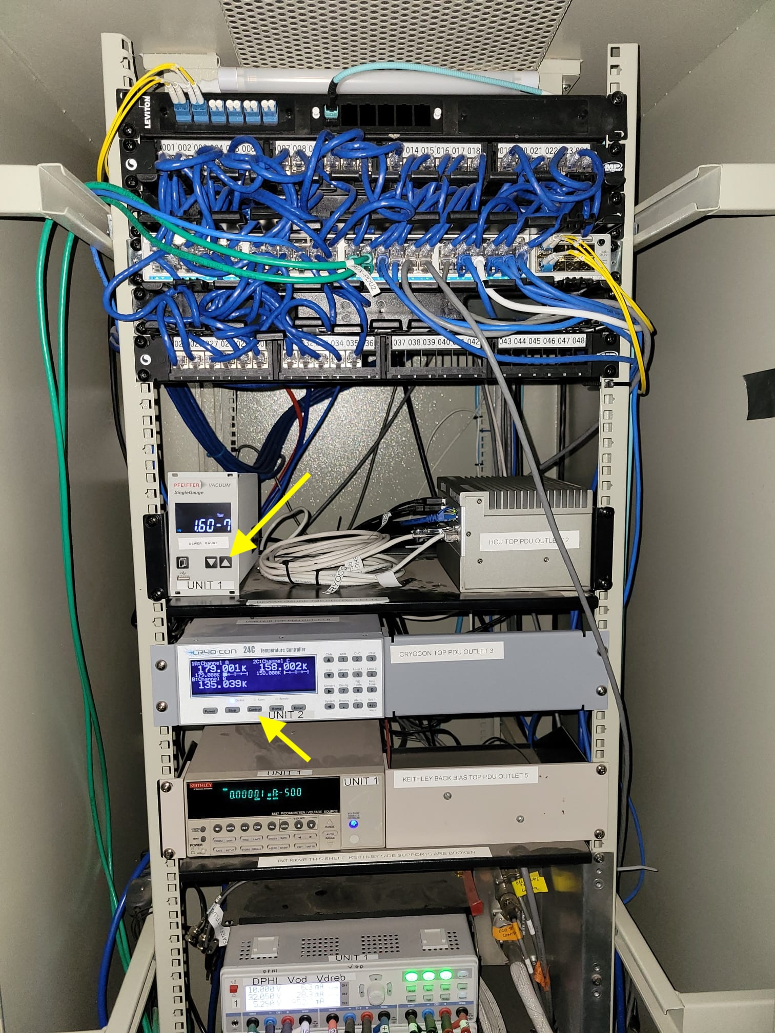
Figure 2: Inside ATCamera main electronics cabinet.
ATMCS/ATPneumatics recovery
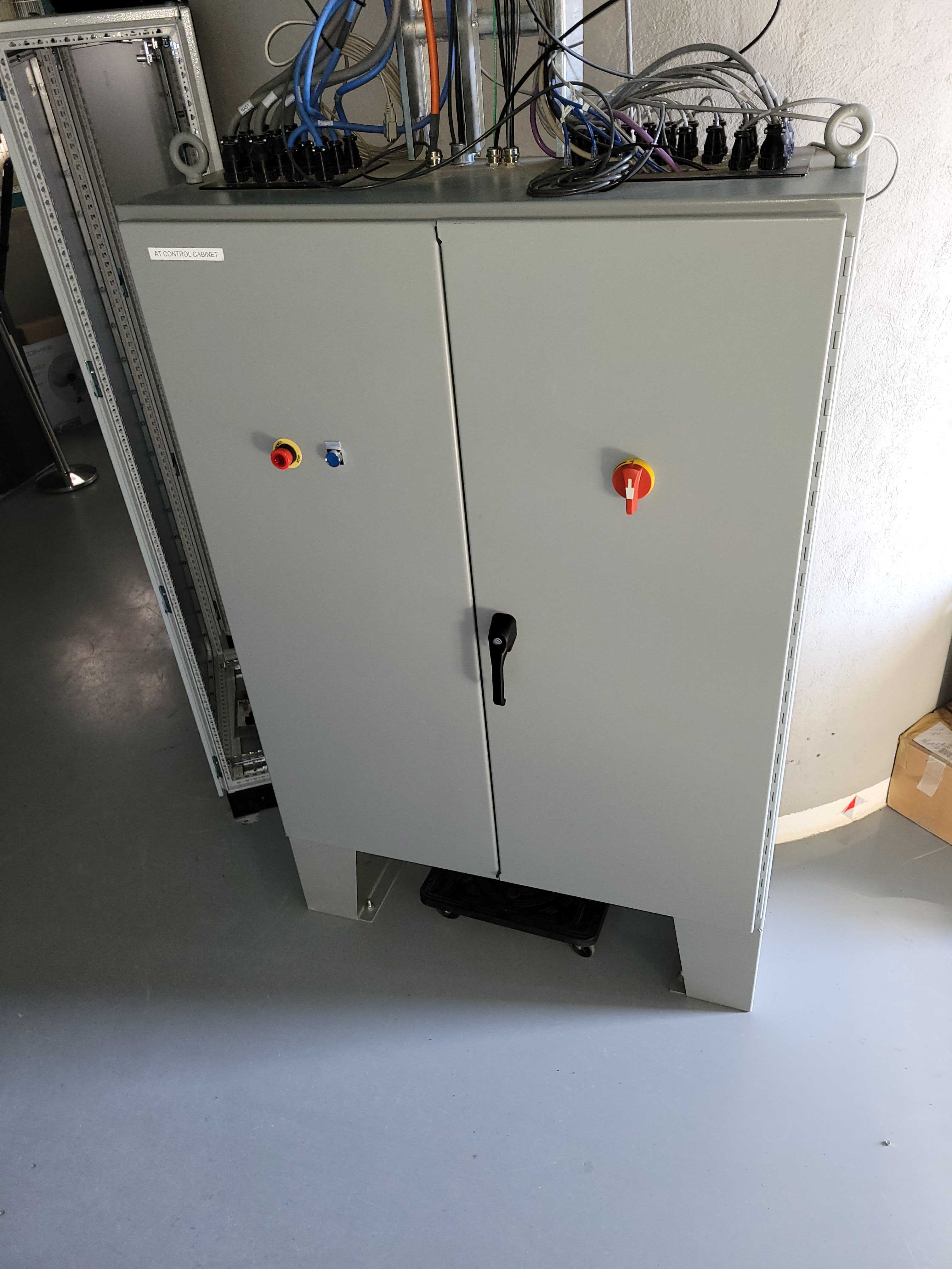
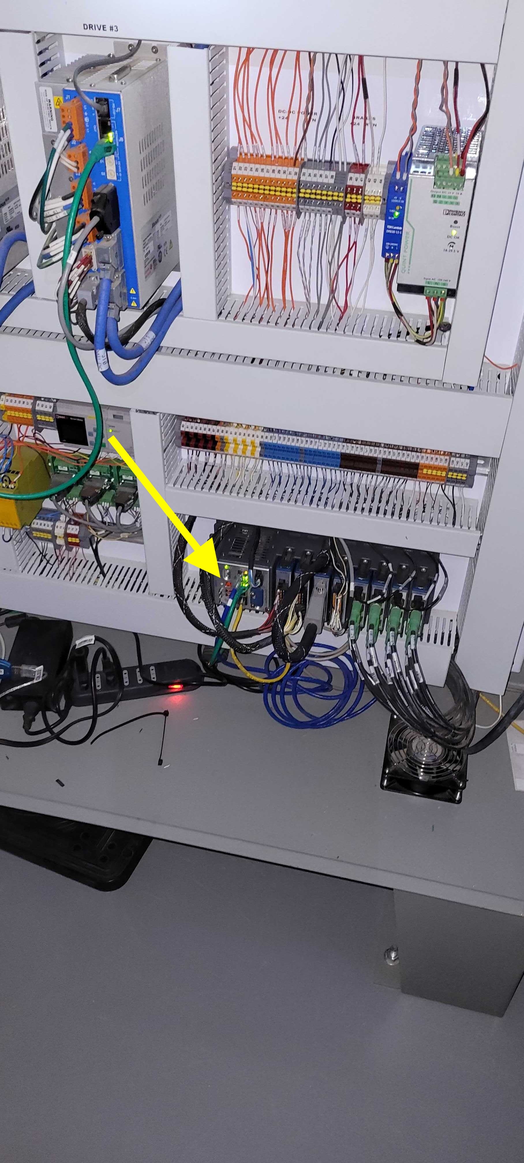
Often the ATMCS and ATPneumatics CSCs will fail to recover after a loss of power or a software upgrade. In this case the ATMCS/ATPneumatics cRIO needs to be rebooted. It is located inside the Main AT Control Cabinet on the first floor, shown in Figures 3 and 4.
Firstly, it is preferred to reboot this cRIO remotely by ssh into atmcs-crio.cp.lsst.org using the credentials in the 1Password vault and sending the restart command:
Open a Terminal.
ssh admin@139.229.170.47
ssh admin@139.229.170.47Search for ATMCS cRIO in 1Password and copy credentials
Send reboot && exit
reboot && exitAfter a minute it should be back.
If remote reboot is not possible, then you must manually reset the cRIO:
ATHexapod recovery
Sometimes the ATHexapod CSC does not recover from a major event. The ATHexapod controller is also located in the Main AT Control Cabinet shown in Figure 3.
In the event of a failure of the ATHexapod CSC:
Power cycle the controller by switching off.
Wait for 3 minutes.
Switch back on.
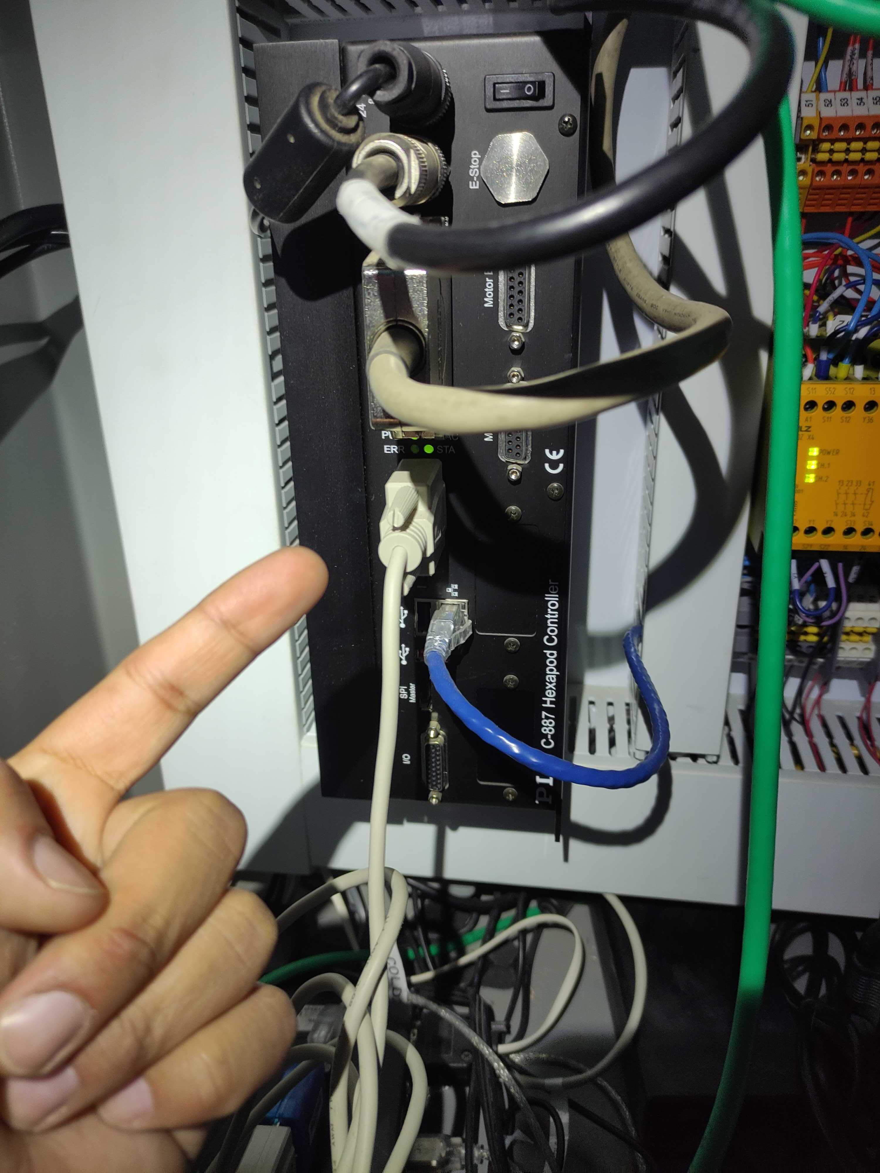
Figure 5: ATHexapod controller inside AT control cabinet.
Note
You can also follow the procedures up to Step 5 in ATHexapod fails to enable with the rest of ATCS for more detailed guidance.
ATCalSys recovery
The ATCalSys generates white and monochromatic light for illuminating the dome screen for calibrations. The system is shown in Figure 6. There are some steps that must be followed after a power loss to recover it.
Ensure that the Safety Gate Bypass is activated. Then, open the safety gate.
Restart auxtel-monochromator01.cp.lsst.org (NUC computer).
Locate the auxtel-monochromator Windows computer in the Illumination System cabinet. After a power failure, this computer does not start automatically.
Important
You need to use a screwdriver to turn the 2 screws to open its door.
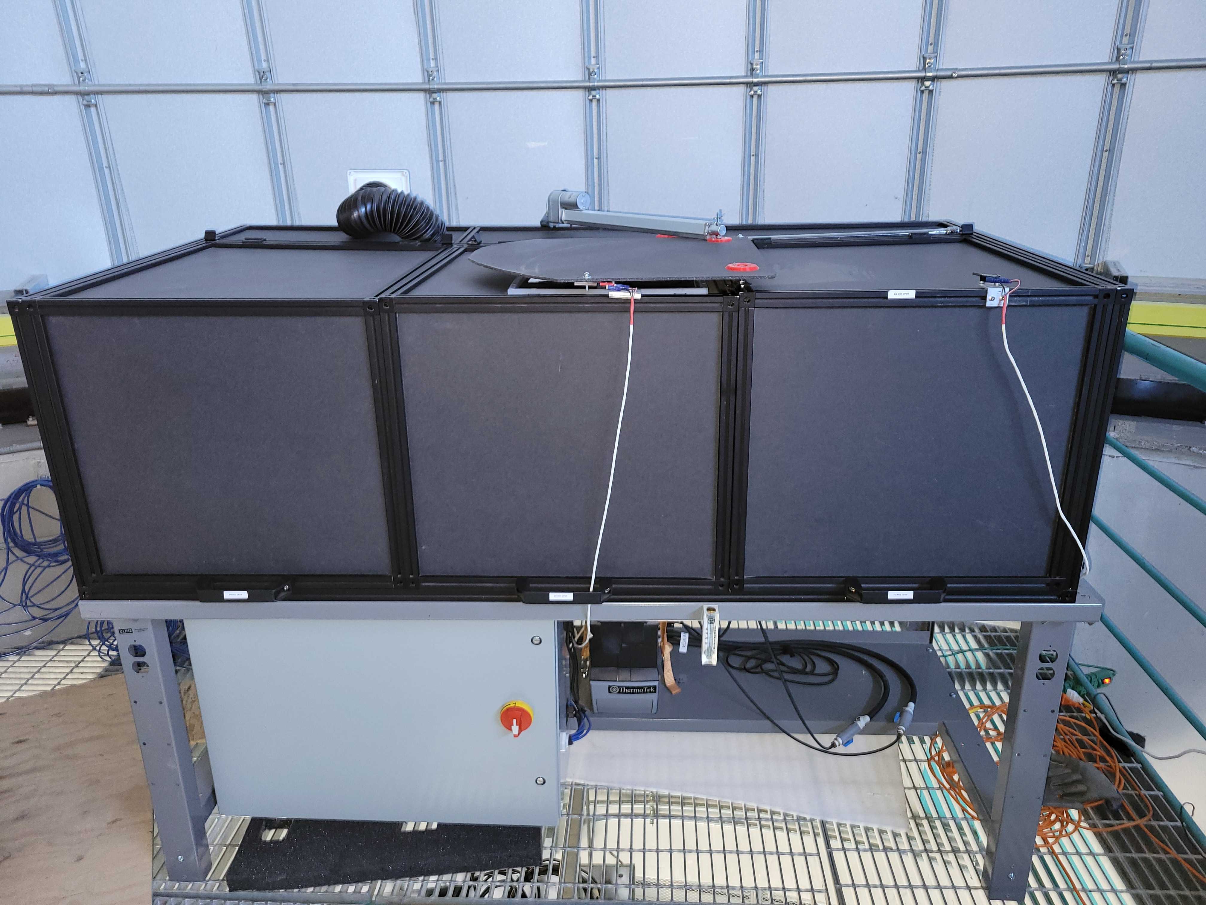
Figure 6: ATCalSys.

Figure 7: Inside the ATCalSys power cabinet.
Press the power button to turn it on. It is a small and round button on the left side of the auxtel-monochromator Windows computer.
Note
A configuration update will remove this step in the future, but for now, it is necessary.
Relaunch LabView
Once the computer is powered on, restart LabView by following the procedures in the AuxTel Illumination System Handbook.
Often the auxtel-ill-control.cp.lsst.org fails to come up properly after a loss of power. In this case, it must be manually restarted.
Locate the computer (top-center device in Figure 7), inside the Illumination System cabinet.
Find the green and orange power connector at the back.
Unplug and replug it to power cycle the computer.
Close the safety gate and Deactivate the Safety Gate Bypass.
After these steps, ATCalSys should be completely recovered. For more information about the illumination system please refer to AuxTel Illumination System Handbook.
ATDome recovery
The AuxTel dome has experienced several problems in the past, most of which have been fixed with the new cRIO hardware and software for ATDome. However, after a shutdown or an unexpected outage, it is always necessary to reboot the components to restore proper operation. More details on interfacing with the ATDome hardware can be found in the technote SITCOMTN-094. The reset procedure is briefly outlined here:
Press the safety gate bypass button on the outside of the main drive cabinet to bypass the safety gate. This allows access to the second floor while ensuring the system does not trigger an Emergency Stop. Once bypassed, open the safety gate.
Reset the Main Box cRIO inside the Dome Main Control Box on the first floor, located between the entrance door and the fan, as shown in Figure 8. Press the reset button briefly (less than one second) to initiate the reboot, indicated by the yellow arrow. This step is necessary to restore control functionality after certain failures or power losses.
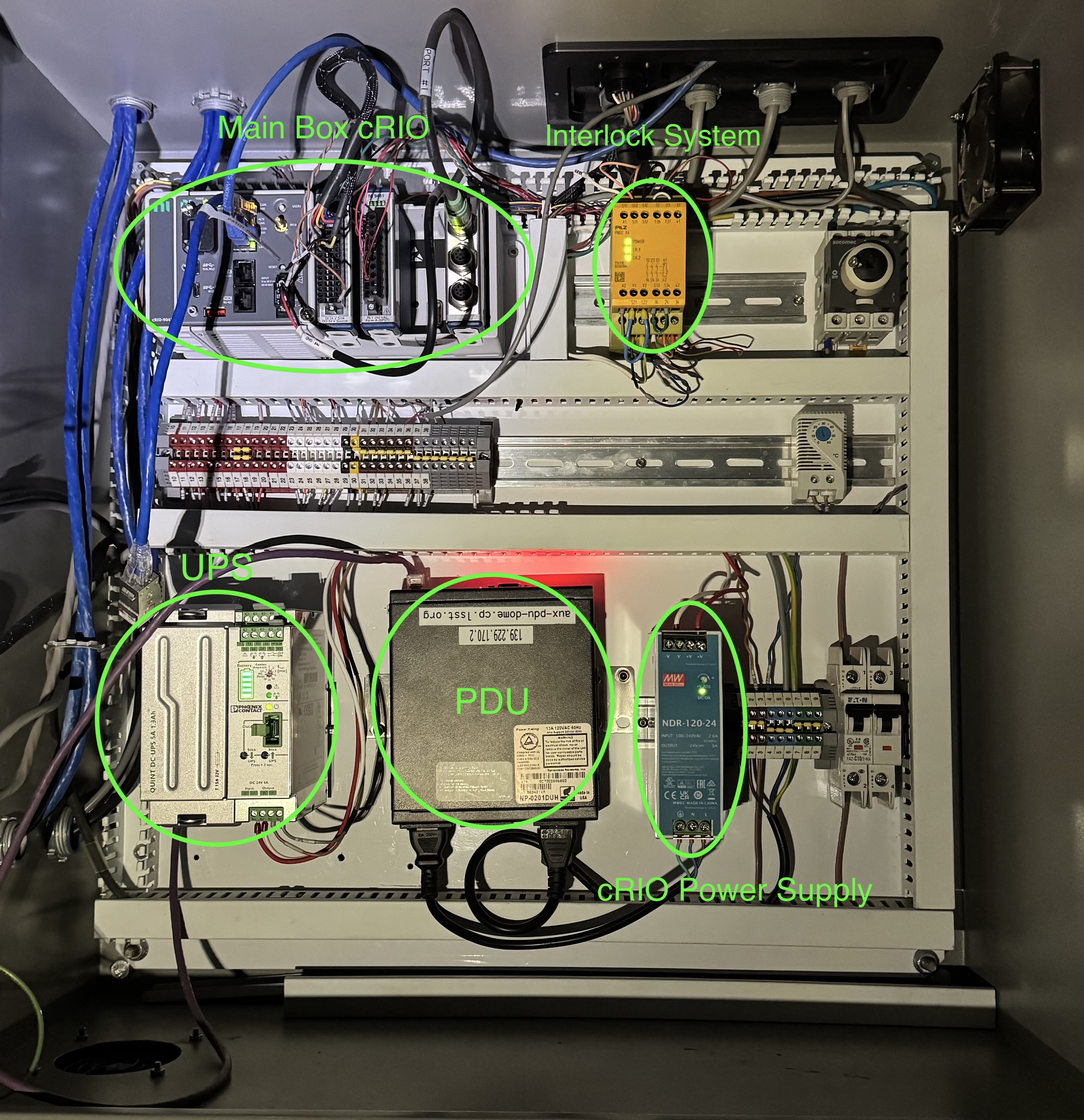
Figure 8: Dome Main Control Box.
Reset the Dome Shutter cRIO inside the Dome Shutter Control Box, located on the second floor and which rotates with the dome. Perform the same reset procedure as with the Main Box cRIO. The reset button is indicated by the yellow arrow.
Important
Always reset the Main Box cRIO first, followed by the Dome Shutter cRIO. Resetting them in the wrong order may cause communication issues.
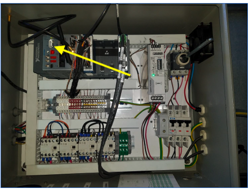
Figure 9: Dome Shutter Control Box.
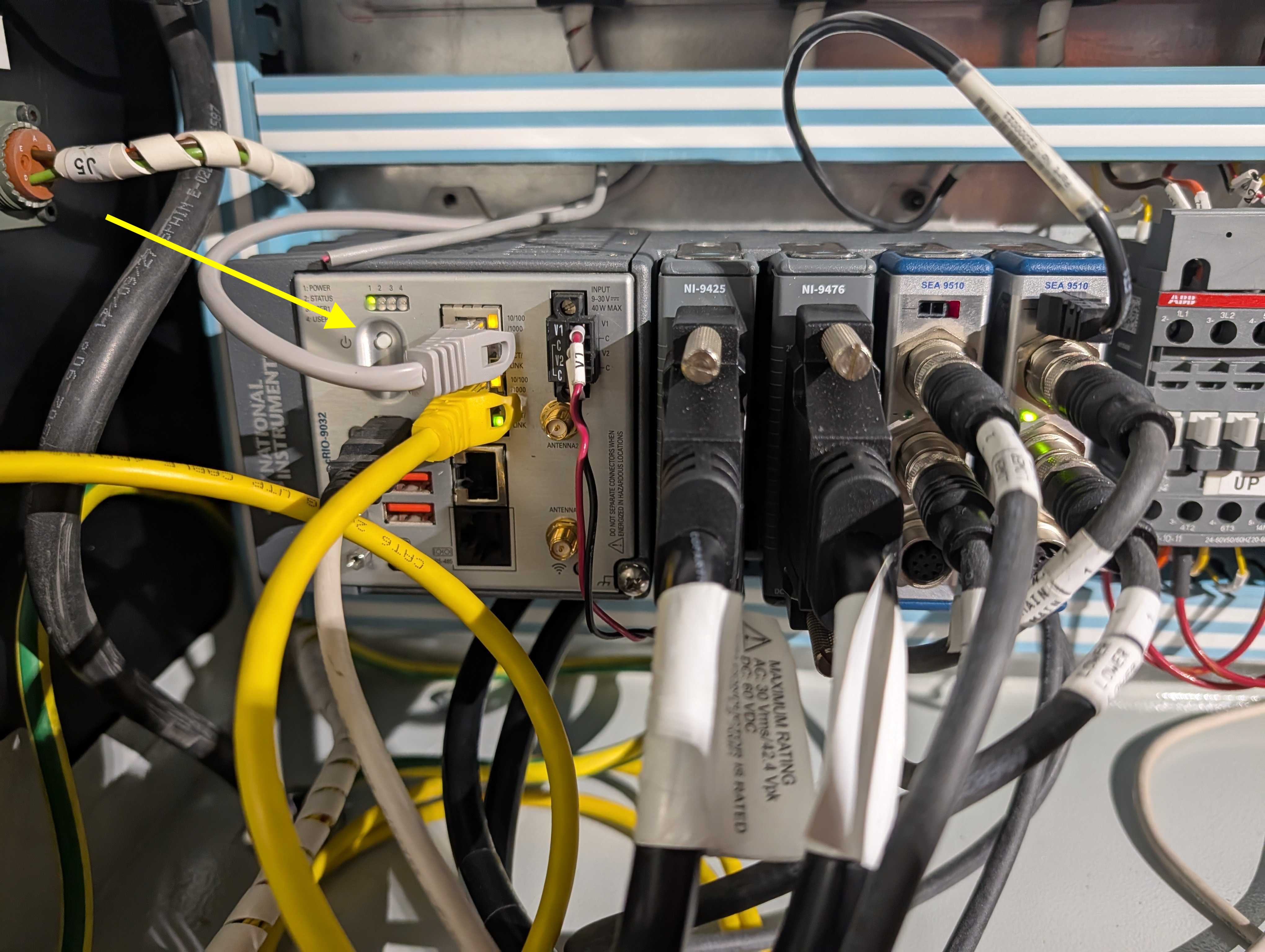
Figure 10: Dome Shutter cRIO.
Close and re-lock the safety gate, ensuring it is securely in place. Then, press the Safety Gate Bypass button again to Deactivate the bypass mode and restore normal safety protections.
Note
The Auxiliary Telescope dome is controlled by a system developed by Astronomical Consultants and Equipment, Inc (Interfacing with the Auxiliary Telescope dome hardware). Low-level control is managed via a telnet interface, allowing operations such as dome rotation and slit opening. Engineering User Interfaces (EUIs) provide status monitoring but offer limited control. The dome’s movement is regulated by a Schneider VFD controller, which adjusts rotation speed and acceleration.
ATCamera recovery
Recovering the ATCamera is the most complex set of steps in this recovery procedure. This procedure assumes that the user is familiar with the CCS Camera Control System software. With the complexity of CCS, this document will not be able to cover all possible things that might go wrong. However, below are outlined some procedures that will deal with most cases. The technote AuxTel PowerUp sequence has detailed information on how to power up the camera.
Step 1 - Assess the status of the CCS subsystems
The easiest way to do this is to open a CCS console:
Log in to auxtel-hcu01
ssh -XY <your login>@auxtel-hcu01.cp.lsst.orgOpen a CCS-console
ccs-console &If you have an M1 Mac, this command will result in a black window. In that case, run this command:
ccs-console -Dsun.java2d.xrender=false -Dsun.java2d.pmoffscreen=false&After the CCS-Console window opens, use the pulldown-menu to launch CCS Tools > Monitoring > Whole Camera > CCS Health.
This should give you a display like Figure 10.
All of the subsystems should be operational. However, after a major event, it is likely that one or more of the subsystems are in Engineering Fault. Proceed with step 2 to clear the faults out of those failing subsystems.
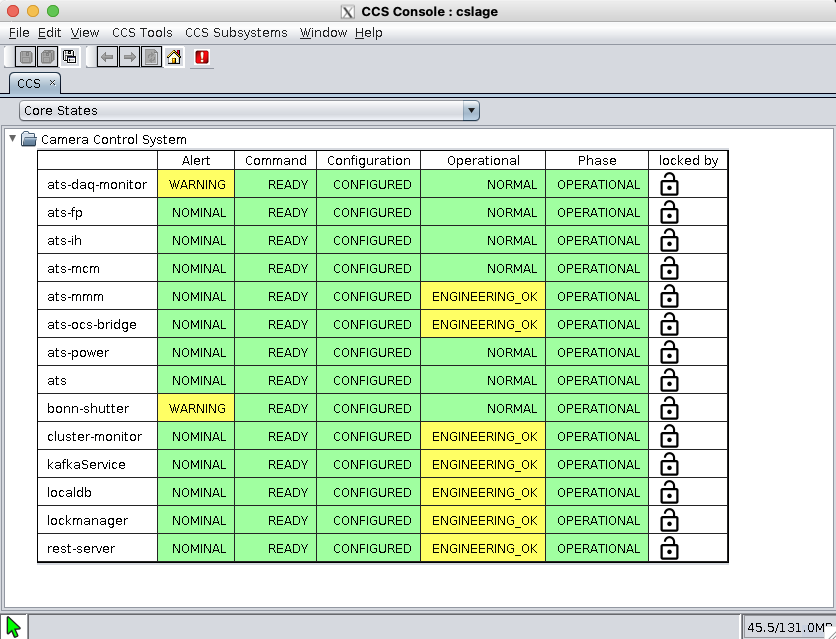
Figure 10: CCS Health display on CCS-Console
Step 2 - Bring the failing subsystems out of fault
Bringing the CCS subsystems out of fault requires interfacing with the CCS Shell. Once you are in the CCS Shell, you can issue commands to the various subsystems. Remember that “tab-complete” is your friend in CCS. If you are not sure what commands are available, try hitting tab to see what it shows you.
Some subsystems operate in different modes: a normal mode and an engineering mode. Some commands are only accessible in engineering mode. Additionally, a lock is placed on a subsystem when certain operations are performed, and it must be removed before the system will operate. Here is an example of bringing one of the subsystems out of fault, in this case ats:
Starts the CCS shell from the bash prompt at auxtel-hcu01.cp.lsst.org:
ccs-shell &Switch to engineering mode and clear alerts:
ccs> ats switchtoEngineeringMode -w
ccs> ats clearAllAlerts -w
ccs> ats switchToNormalMode -w
Using the clearAllAlerts command will usually allow you to clear most of the subsystem faults after a major event. However, there are some exceptions:
- The ats-mcm (which stands for Master Control Module) can only be cleared this way once other systems are out of alert states. As such it should be cleared last.
To clear the alert on ats-mcm, run the following command in ccs-shell:
ccs> ats-mcm clearAllAlerts -w
Important
The ats-mcm does not automatically clear its alert state, it always requires a command to do so. Restarting the ats-mcm is not a recommended solution and should not be attempted by the observing team. If this issue persists, report it in #summit-auxtel or call for an expert.
- If the WREB board has not been powered up, then ats-fp will not be reporting.
This requires starting up the WREB board with the
ats-init.pyscript, followed by turning on the HV bias. Detailed instructions for starting up the WREB and turning on the HV are available in the powering up from a completely cold state section of the SITCOMTN-026.
- Sometimes, bonn-shutter has a fault which can not be cleared with the instructions above.
When this happens, the only way that has been found to clear this is to physically power cycle the shutter controller. Figure 11 shows the location of the bonn shutter controller. Power cycle it by unplugging the power cable, waiting a few seconds, and plugging it back in. This usually clears the fault.
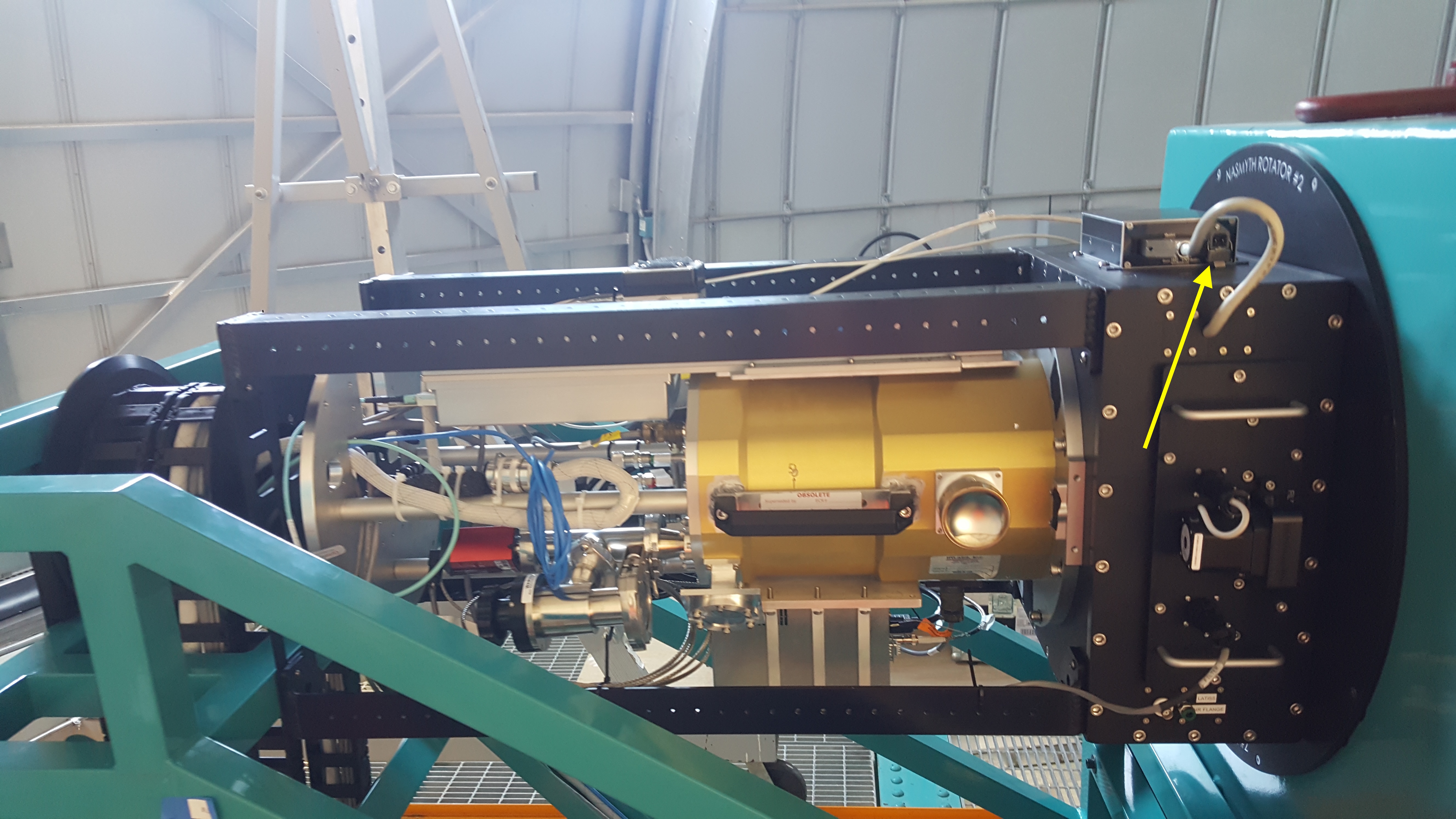
Figure 11: Power cycling the bonn-shutter controller.
Step 3 - Bringing ats-ocs-bridge to the proper state
One of the CCS modules is ats-ocs-bridge. This is the subsystem that interfaces between CCS and the Observatory Control System (i.e. the CSCs). In this case ats-ocs-bridge is interfacing with the ATCamera CSC. It is necessary to get ats-ocs-bridge into the proper state in order to be able to control ATCamera with LOVE and the ScriptQueue. Here are the necessary steps:
Get the state of the atc-ocs-bridge running the command from the ccs-shell:
ccs> ats-ocs-bridge getState
This will return something like:
ccs> ats-ocs-bridge getState¶AlertState:NOMINAL CCSCommandState:IDLE CommandState:READY ConfigurationState:CONFIGURED OfflineState:OFFLINE_PUBLISH_ONLY OperationalState:ENGINEERING_OK PhaseState:OPERATIONAL SummaryState:OFFLINE
- The SummaryState is the same state of ATCamera you see with LOVE.
If the SummaryState is
FAULT, it cannot be brought out of fault with the normal LOVE commands. It needs to be brought out of fault with the ccs-shell commandccs> ats-ocs-bridge clearFault -w
- Assuming the SummaryState is
OFFLINE, then we look at the OfflineState. If the OfflineState is
OFFLINE_PUBLISH_ONLY, we need to transition it toOFFLINE_AVAILABLEbefore we can use the usual state transition commands in LOVE and the script queue to bring it online. This is done with the ccs-shell commandccs> ats-ocs-bridge setAvailable -w
- Assuming the SummaryState is
- Transition ATCamera to
STANDBY Once we have it in SummaryState
OFFLINEand OfflineStateOFFLINE_AVAILABLE, the ATCamera can transition using the script queue and theset_summary_state.pyto bring the SummaryState toSTANDBY.
- Transition ATCamera to
- Transition LATISS to
ENABLED Once the SummaryState is
STANDBY, you can runenable_latiss.pyin the script queue to bring up all of LATISS. If this is successful, things should now be operating normally.
- Transition LATISS to
ATSpectrograph Recovery
In the case the ATSpectrograph needs to be recovered, follow the procedure from ATSpectrograph recovery.
Contingency
If the procedure was not successful, report the issue on the #summit-auxtel channel and/or activate the Out of hours support.
This procedure was last modified Jun 24, 2026.